
Analog Audio Compressor
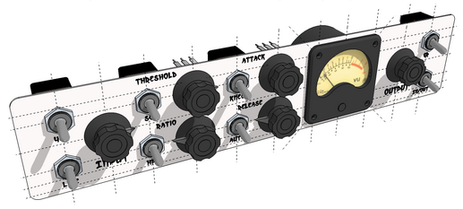
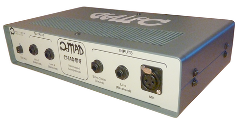
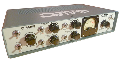
The idea was to design and build a modern, studio-grade, fully-analog VCA audio compressor with a somehow 'vintage' look & feel. The objective was to get as close as possible to something looking as a real product.
It is based on several design notes from THAT Semiconductors®, the main one being Design Note 115.
Yet, functionalities have been well extended with:
A pre-amplifier stage to offer both Mic/Line balanced inputs
48V Phantom power for capacitor Mic biasing
Side-chain external input for ducking applications
100Hz high-pass filter for audio/side-chain with selectable path
Analog VU-Meter
Driver for dual Line-level balanced outputs
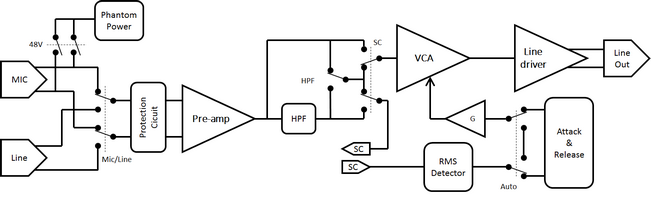
The heart of the compressor is a THAT4301 dynamics processor including both VCA and RMS detector.
1. Schematics Analysis & Simulation
Main Board Schematics
Power Supply Board
Compression Analysis
The audio input signal is routed to both the VCA and the RMS envelope detector. Let-us focus on the way gain controlled is applied.
The RMS detector provides a rectified output voltage, which is a logarithm function of the audio RMS amplitude. It is therefore proportional to the input dBu level:
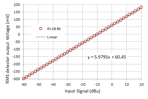
On the above graph, the measured RMS detector gain is in agreement with the specified 6mV/dBu.
The RMS envelope signal VRMS is then summed up with a DC voltage controlled by the Threshold potentiometer Vth, acting up like a tunable offset applied to VRMS:
Where k1 and k2 are set by resistors ratio.
Because the summing stage is also an inverting-rectifying stage, only negative part of V'RMS are kept. In other terms, gain correction is only applied when:
That's where the Threshold operates!
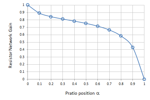
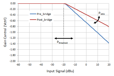
Next, the V'RMS signal is applied to a resistor bridge including the Ratio potentiometer. The resistor network apply a variable gain {0→1} which is a non-linear function of the potentiometer position:
The plot below show the static Vctrl (V) resulting from input signal (dBu) obtained with:
Threshold potentiometer @ 30%
Ratio potentiometer @ 80%
Next, the Attack and Release stage is basically an asymmetric rate (speed) limiter for Vcrtl. It is made of two tunable current sources charging (Release) and discharging (Attack) a capacitor at dialed rates. The whole stage is loop-closed so that output voltage Vctrl_AR tries to 'follow' Vctrl.
Vctrl_AR is finally summed up with another DC voltage sets by the Makeup potentiometer, before being send to the inverting input ec- of the VCA gain controller.
Again, k3 and k4 are set by resistors ratio. Vmakeup brings the desired offset to Vctrl_AR thus modulating the static gain reduction, and therefore the output average volume after compression. After the 4301 datasheet, the global VCA gain reduction constant on ec input is about 6mV/dB.
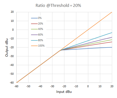
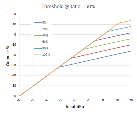
The plots below show the global static gain reduction for various Ratio and Threshold settings. Makeup is set to zero. It basically shifts the results vertically when engaged.
SPICE® simulations
RMS envelope detector:
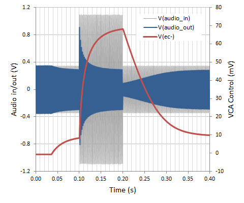
Attack & Release circuit:
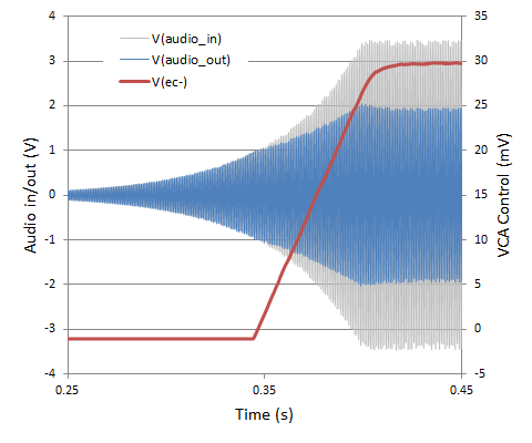
Compression Ratio (exponential increase of the input signal amplitude):
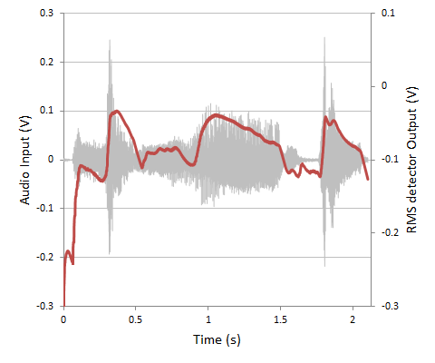
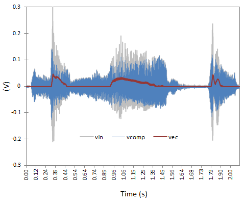
Test with real audio input signal:
2. Fabrication
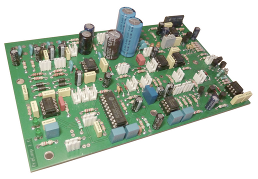
Main board assembly:
Final product:
- Log in to post comments