Clonewheel Organ
A clonewheel organ is an electronic musical instrument that emulates (or "clones") the sound of the electromechanical tonewheel-based organs formerly manufactured by Hammond from the 1930s to the 1970s. Clonewheel organs generate sounds using solid-state circuitry or computer chips, rather than with heavy mechanical tonewheels, making clonewheel organs much lighter-weight and smaller than vintage Hammonds, and easier to transport to live performances and recording sessions.
The phrase "clonewheel" is a play on words in reference to how the original Hammond produces sound through "tonewheels". The first generation of clonewheel organs used synthesizer voices, which were not able to accurately reproduce the Hammond sound. In the 1990s and 2000s, clonewheel organs began using digitally-sampled real Hammond sounds or digital signal processing emulation techniques, which were much better able to capture the nuances of the vintage Hammond sound.(https://en.wikipedia.org/wiki/Clonewheel_organ)
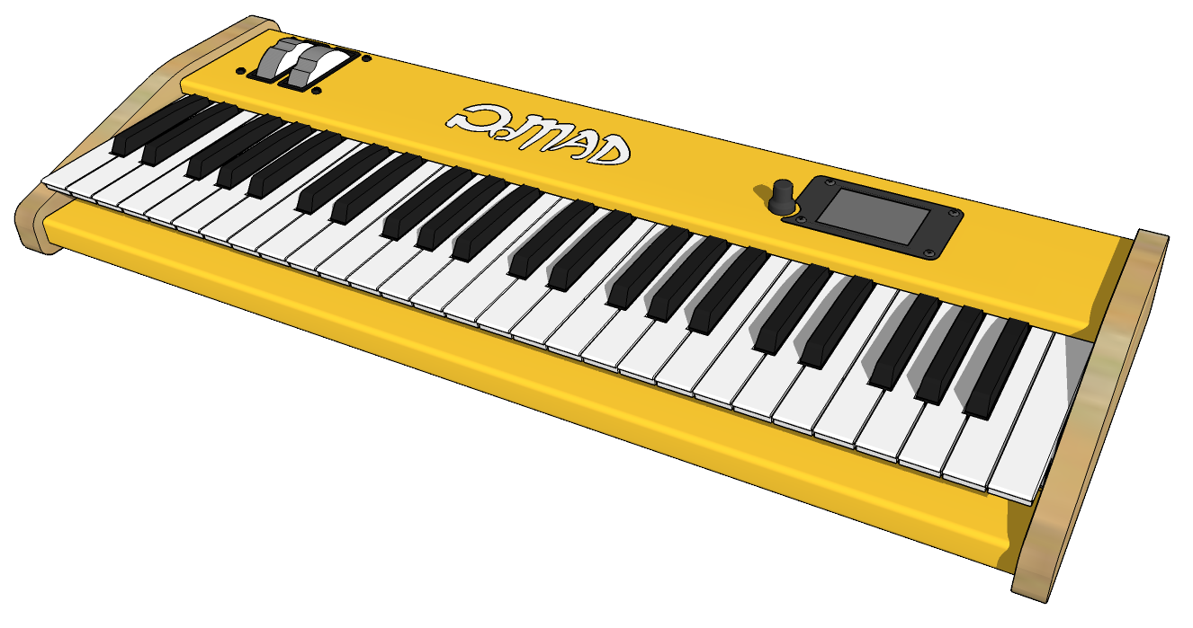
Main characteristics
9 Drawbar (tone wheel) additive sound synthesis based on wave table interpolation
48kHz simple-precision floating point calculations
16-bit / 48kHz DAC ouput
16 voices polyphony (@~70% CPU usage, up to 20 voices shouldn't be a problem)
Per-voice percussion sound (interpolated sinewave)
Per-voice envelope generator (not true to tone wheel organs, yet good to have)
Amp section with smooth distortion
FX : Vibrato, Tremolo, Delay, 4-voices stereo Chorus, Stereo Rotary Speaker, Flanger
Dry/Wet/Feedback mixing stage
MIDI In/Out interface
Octave/Semitone transposition
Pitch-bend and modulation wheels
100 presets can be saved/loaded from SD card (UI module functionality)
The organ is an assembly of few modules:
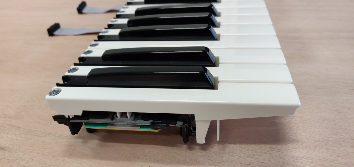
FATAR TP/9S synthesizer keybed
mkcv64smf MIDI Encoder board from MIDI Boutique
ST Microelectronics Nucleo H743ZI development board
Custom designed PCB audio shield for Nucleo (including AKM codec, Audio In/Out and MIDI front-ends, SDRAM for delay based effects, SD card for samples...)
Custom designed UI module based on STM32F411 µC and touch panel TFT display from Mikroelektronica
At this moment, there is no built-in Reverb effect, since this is something commonly found in mixing consoles. Although, I did consider adding an external Reverb unit such as one based on SPIN semiconductor FV-1 chip from Electro-Smith. Or a spring reverb, why not...
Also, the organ is not velocity sensitive. Yet, velocity is already available in the firmware data structure, so it shouldn't be hard to use this to modulate the envelope generator. I just didn't try...
Hey, and there's no sustain pedal. The jack plug is there, but not wired :-). Again, that shouldn't be too challenging to add this functionality to the envelope generator. I'm not that confident regarding the max polyphony...
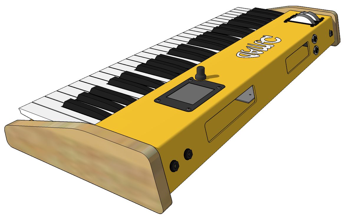
Organ parameters and user interface
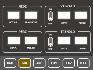
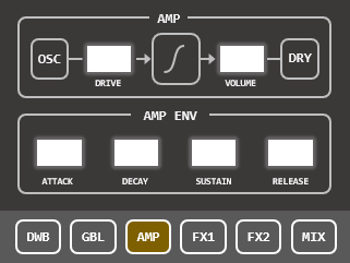
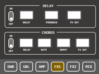
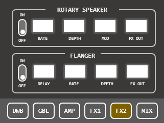
The sound of the organ is shaped by means of no less than 48 parameters:
| 0 | g_drawbar[0] | Drawbars | Level [0..8] +3dB/step |
| 1 | g_drawbar[1] | Level [0..8] +3dB/step | |
| 2 | g_drawbar[2] | Level [0..8] +3dB/step | |
| 3 | g_drawbar[3] | Level [0..8] +3dB/step | |
| 4 | g_drawbar[4] | Level [0..8] +3dB/step | |
| 5 | g_drawbar[5] | Level [0..8] +3dB/step | |
| 6 | g_drawbar[6] | Level [0..8] +3dB/step | |
| 7 | g_drawbar[7] | Level [0..8] +3dB/step | |
| 8 | g_drawbar[8] | Level [0..8] +3dB/step | |
| 9 | g_octave | Transposition | Octave [-2..+2] |
| 10 | g_transpose | Semitone [-12..+12] | |
| 11 | g_vibrato_sw, | Vibrato | Switch [On/Off] |
| 12 | g_vibrato_rate | Rate 1/10 Hz | |
| 13 | g_vibrato_depth | Depth [0..99] | |
| 14 | g_perc_pitch | Percussion | Pitch [1..8] |
| 15 | g_perc_amount | Amount [0..99] | |
| 16 | g_tremolo_sw, | Tremolo | Switch [On/Off] |
| 17 | g_tremolo_rate | Rate 1/10 Hz | |
| 18 | g_tremolo_depth | Depth [0..99] | |
| 19 | g_amp_drive | Amp distorsion | In Level [0..99] |
| 20 | g_amp_volume | Out Level [0..99] | |
| 21 | g_amp_env_attack | Amp ADSR | Time [0..99] |
| 22 | g_amp_env_decay | Time [0..99] | |
| 23 | g_amp_env_sustain | Level [0..99] | |
| 24 | g_amp_env_release | Time [0..99] | |
| 25 | g_delay_sw, | Delay FX | Switch [On/Off] |
| 26 | g_delay_delay | Delay ms/10 [0..99] | |
| 27 | g_delay_fbk | Feedback amount [0..99] | |
| 28 | g_delay_out, | Ouput level [0..99] | |
| 29 | g_chorus_sw | Chorus FX | Switch [On/Off] |
| 30 | g_chorus_delay | Delay ms/10 [0..99] | |
| 31 | g_chorus_rate | Rate 1/10 Hz | |
| 32 | g_chorus_depth | Depth [0..99] | |
| 33 | g_chorus_out | Ouput level [0..99] | |
| 34 | g_rotary_sw | Rotary Speaker FX | Switch [On/Off] |
| 35 | g_rotary_rate | Rate 1/10 Hz | |
| 36 | g_rotary_depth | Depth [0..99] | |
| 37 | g_rotary_mod | Amplitude modulation [0..99] | |
| 38 | g_rotary_out | Ouput level [0..99] | |
| 39 | g_flanger_sw | Flanger FX | Switch [On/Off] |
| 40 | g_flanger_delay | Delay ms/10 [0..99] | |
| 41 | g_flanger_rate | Rate 1/10 Hz | |
| 42 | g_flanger_depth | Depth [0..99] | |
| 43 | g_flanger_out | Ouput level [0..99] | |
| 44 | g_mix_dryout | Output Mixer | Dry signal ouput level [0..99] |
| 45 | g_mix_fxout | FX signal ouput level [0..99] | |
| 46 | g_mix_dryfbk | Dry signal feedback level [0..99] | |
| 47 | g_mix_fxfbk | FX signal feedback level [0..99] |
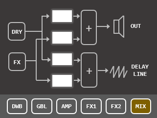
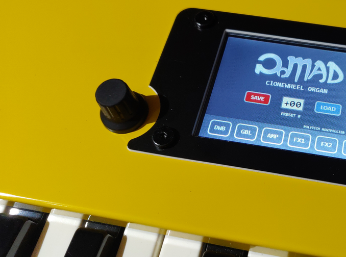
These parameters are dialed using a single rotary encoder in association with a touch panel selection. User interface is made of 7 quite self explanatory panels:
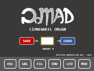 | ||
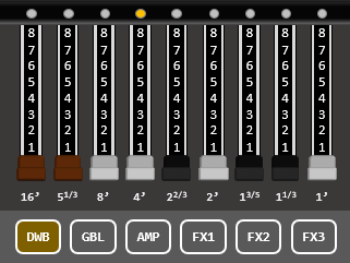 |  |  |
 |  |  |
Hardware architecture
Keybed and MIDI encoder
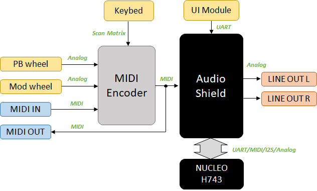
For this prototype, the choice has been made to fabricate a complete organ keyboard. The keybed electronics is simply a passive matrix of contacts (a double matrix actually to measure velocity) that requires sequential row activation and column scanning to detect actions on keys. That's the purpose of the MIDI encoder board. Considering the price of the MIDI encoder added to the price of the keybed (not mentioning the fact that FATAR keybeds are not widely distributed), a much cheaper solution would have been to buy an entry-level master keyboard with MIDI output and connect it directly to the MIDI input of the audio shield. I would recommend this approach to anyone willing to test the organ synthesis first. Nevertheless, the FATAR TP/9S is nice under the fingers, so there's no regrets here... but the solution is expensive for a DIY project. Also, we could have developed our own MIDI encoder... but to be honest, there was no excitement here...
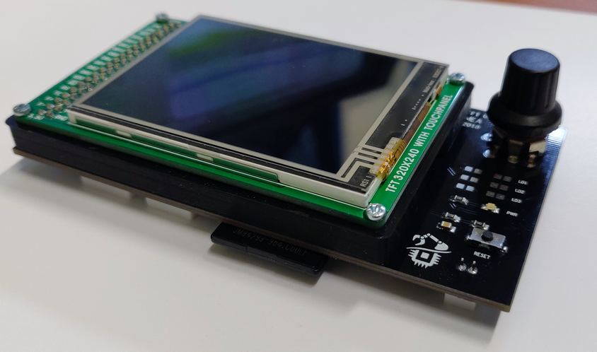
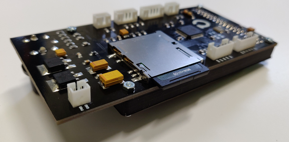
UI module
Given the important number of synthesis parameters we want to play with, the need of a simple method to transfer parameter values during runtime appears very early in the development process. There are many solutions including the use of GPIOs, potentiometers (which limits the number of channels), or issuing commands via the UART debug console. This last approach was preferred but instead of issuing console commands manually, a dedicated board has been designed around a touch screen display and a STM32F411 device. Having a separated module, with its own processor, for the single purpose of the user interface sounds a little bit overkill. But it is nice to think that the main CPU is entirely devoted to audio processing. Also, by keeping the architecture modular, parts may be reused in further projects.
The UI module "only" manages the touch panel display and sends a frame containing the 48 bytes (parameter values) every 200ms. Such time interval is enough for the reactiveness of the organ, and does not keep the receiving CPU too busy, but it would not permit real-time data such as modulation wheels to be transmitted this way. That's the reason why modulation wheels data are sent via MIDI CC message using the MIDI encoder board.
The UI module features its own SD card socket so that parameter sets can be saved and reloaded as presets. The reason for limiting the presets number to 100 is just that UI data field that displays the preset number was limited in size :-) A shame...
 |  |
Nucleo H743ZI and Audio Shield
As its name suggests, the Nucleo H743ZI board features a high-end STM32H7 device with CPU running at 400MHz, with quite a lot of memory (2MB Fash, 1MB RAM), a plethora of peripherals including Serial Audio Interface (of special interest here), and DSP capability due to its embedded FPU.. That beast is widely available for a modest 25€ price everywhere. A reason for choosing high-end MCU was to explore the question: how much audio processing can we ask to a device that's still categorized into the microcontroller family, and therefore not competing with multi-core Cortex-A processors found on Raspberry Pi and the like, given that here, only low-level programming is involved without the load of an OS layer such as Linux or Android.
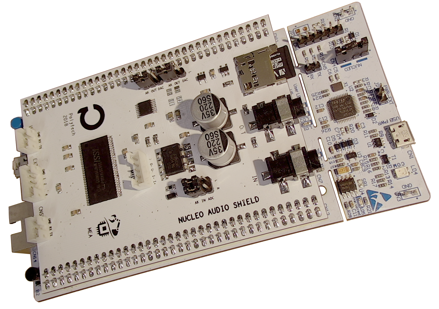
Yet, a specific shield devoted to audio applications has been designed to ease connections of external circuitry such as:
Opto-isolated MIDI In/Out interface
Line-level buffered stereo In/Out interface
AKM AK4554 professional codec (ADC & DAC) wired to STM32 SAI interface
64Mbit external RAM (for effects or samples storage)
SD card slot (for parameters and samples storage)
I/O connectors for custom controls or communication interfaces (UART)
For those not in the mood of assembling such a shield, you may consider using commercially available breakout boards for audio converters (see Sparkfun), or even use the MCU embedded DACs that 'only' feature 12-bit resolution but might sound quite well. One limiting factor through, would be the availability of an external RAM for delay-based effects (delay, chorus, flanger, ...). Using the internal RAM is possible but will shorten the length of the delay line.
Below figure represents the hardware architecture of the actual prototype:
Mechanical assembly
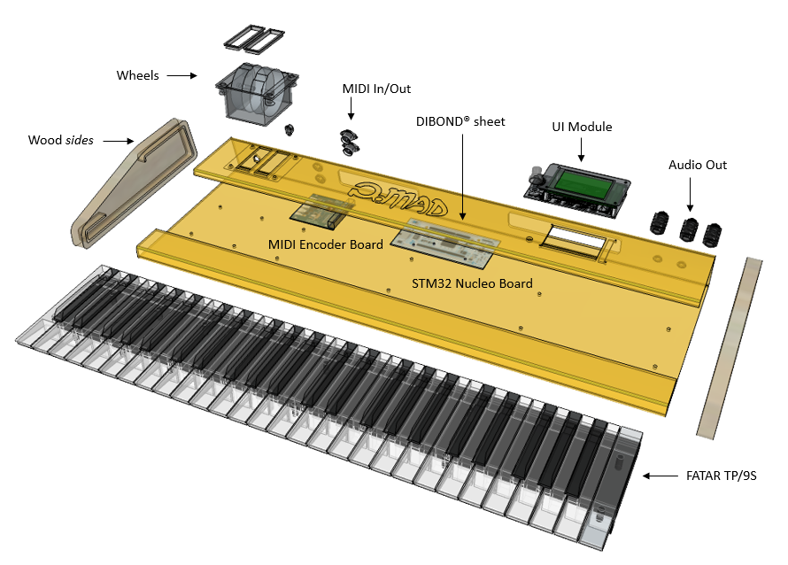
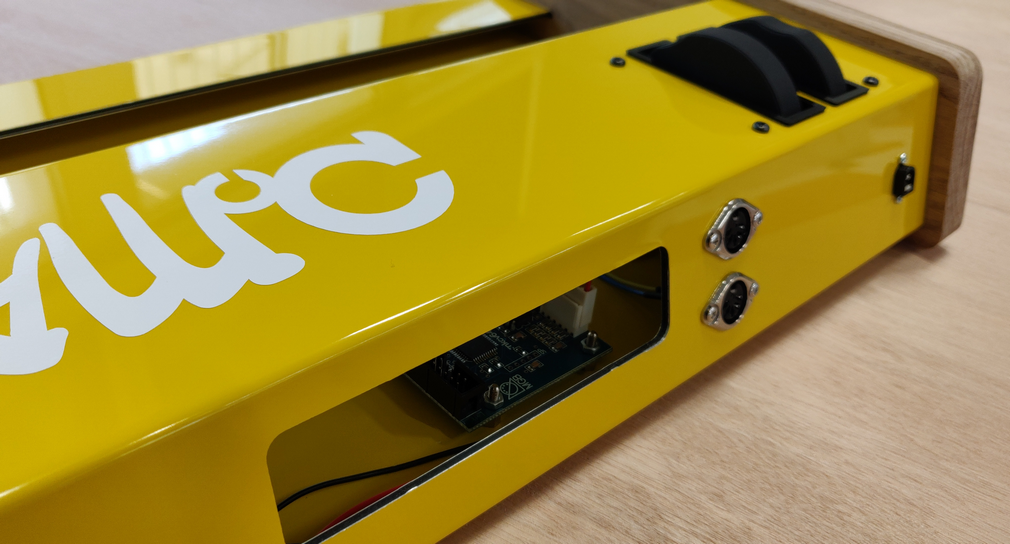
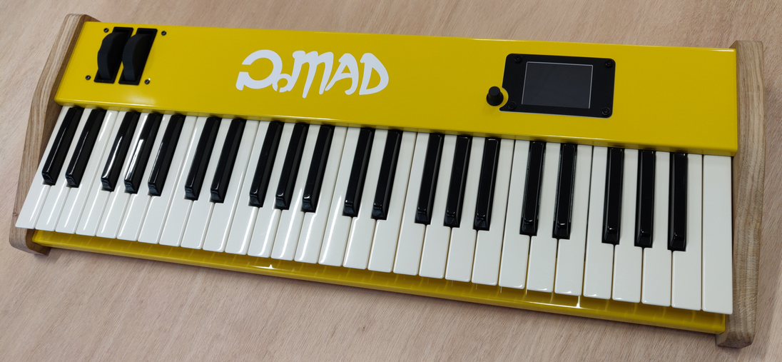
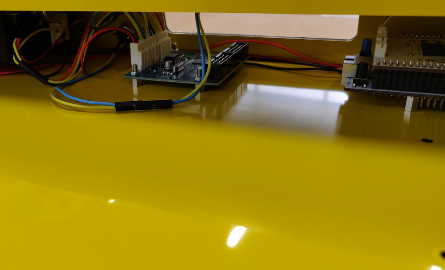
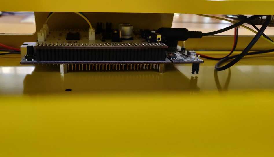
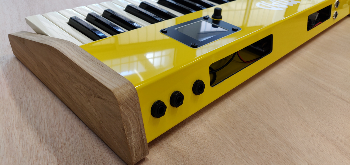
The picture below shows the whole mechanical assembly. What gives a professional look is undoubtedly the folded DIBOND® composite sheet, which was obtained using CNC to deep cut grooves where folding was desired. The subsequent folding turned out to be quite easy, without tools but bare hands... CNC was also involved for all the openings, the oak sides fabrication and other small parts. 3D printing was used for finishing wheel frames. Large back openings serve several purposes: LED visibility, access to programing and debug interfaces, ventilation, easy access to keybed connectors for assembly, and last but not least, access to CPUs reset buttons :-) Well that's how the MIDI 'panic' feature works here...
Firmware
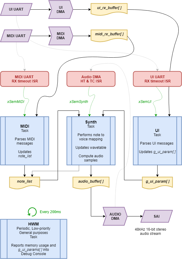
Below is a global view of the firmware architecture based on FreeRTOS and low-level (no HAL libraries) programming.
Processes are built upon :
3 DMA routing to achieve true hardware parallelism regarding:
MIDI message reception and buffering (UART → memory)
UI message reception and buffering (UART → memory)
Audio stream up to the audio analog outputs (memory → SAI)
3 Interrupts for immediate action when
Audio stream requires new samples to be computed (DMA HT and TC interrupts).
New MIDI message has been received (UART RX timeout interrupt)
New UI message has been received (UART RX timeout interrupt)
4 Tasks
vTaskMIDI is triggered by the MIDI UART interrupt by means of a binary semaphore. It parses MIDI messages and performs update into a global dynamic list note_list of notes (keys) to be played. It also parses MIDI CC events and take care of PB and Modulation wheel states
vTaskUI works pretty much the same way with the UI UART, updating the global g_ui_param[] array of organ settings (48 parameters) every time a frame is received from the UI module
vTaskSynth is the core of the synth engine. It is triggered by the audio stream DMA each half-buffer end of transmission. The buffer is 1440 16-bit sample deep. Given that it is stereo, the DMA interruption occurs every (1440/2)/2 = 360 audio samples. At 48kHz, this happens every 7.5ms. That's an acceptable latency, but I guess working with sightly smaller buffer would work up to some extends. I didn't try... This task has the higher priority level.
vTaskHMW is a general purpose, debug-oriented task that periodically reports into console thru printf(). It is primarily used to monitor FreeRTOS memory usage, and stacks High Water Marks (which explains that name...). It has the lowest priority level.
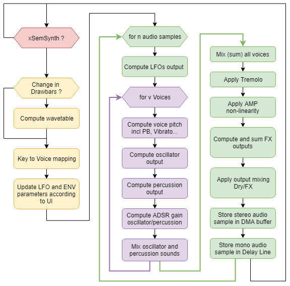
The chart below represents detailed execution of the synthesis task. You may notice that:
UI parameter changes (including drawbar registration) and keyboard action are only taken into account every time the task is executed (not at sampling time); i.e. every 7.5ms
PB and Modulation wheels are updated at sample rate
Oscillator, vibrato, percussion and ADSR envelope are computed for each voice being played (up to 16)
Tremolo, distortion and FX are computed once per sample, after active voices have been summed up
The key-to-voice mapping is maybe the toughest part because you need to take into account several casual situations, such as the limited number of voices or notes that play beyond the note-OFF event due to release time. I couldn't manage to have clean code here, although it seems to work. In its actual software version, the audio processing uses 70 to 80% of CPU time (16-voices playing with effects) under gcc -O1 compilation optimization settings.
Audio examples
Here are two audio demos originally recorded with organs. The organ is hardware-controlled by MIDI sequences downloaded from www.midiworld.com. The audio output is fed back to the computer, recorded and mixed with virtual instruments for drums and bass tracks. There are no software EQ or FX plugins on the organ sound. What you hear is raw audio from STM32 synthesis. Master mix has been leveled before rendering.
Light my fire, by the Doors (MIDI track)
Drawbar Registration : 876001215
Percussion engaged (pitch 6, amount 50%)
Vibrato, 120ms delay, and Rotary Speaker effect engaged
Distortion stage drive to 70%
House of rising sun, by the Animals (MIDI track)
Drawbar Registration : 888000000
Percussion engaged (pitch 6, amount 20%)
Vibrato and Chorus effect engaged
Distortion stage drive to 80%
Picture Gallery
Resources
Audio Shield Schematics
UI Module Schematics
Firmware
Mechanical
- Log in to post comments
