
1.4. Hello World #3
In this tutorial, we will simply get the previous "Mr Robot" LED-blinking example running from within STM32CubeIDE .
Start STM32CubeIDE within your dedicated workspace (workspace_tuto).
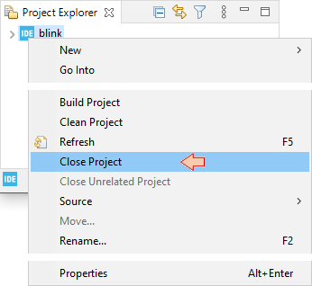
At this moment, your workspace only contains the blink project done before with the Cube/HAL approach. In the project explorer, Right-Click on the project and close it.
1. Creating a new project
Because we want to avoid any automatic import from STM32CubeIDE, let us start a new project with no template. This is achieved by selecting from the main menu: File→New→Project.
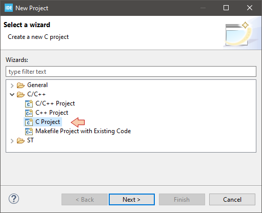
In the New Project dialog, select C Project.
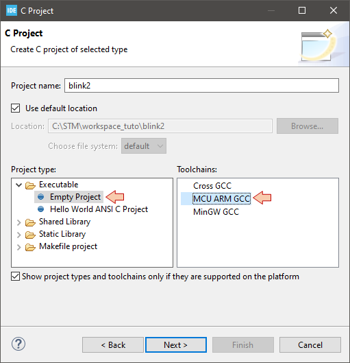
In the C Project dialog, provide a name for the project ("blink2" for instance) and choose Empty Project as project type and MCU ARM GCC for the toolchain. Then click Next.
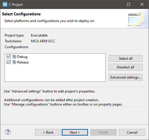
Leave the Select Configurations options as it is, and click Next.
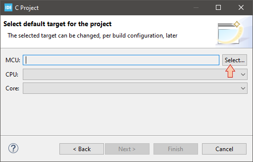
Then you're asked for the target CPU. Click the Select... button.
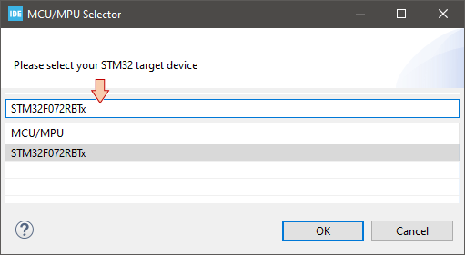
Use the MCU/MPU Selector dialog to fill the target field with your MCU part number. Here we have an STM32F072RBTx microcontroller. When done, click OK.
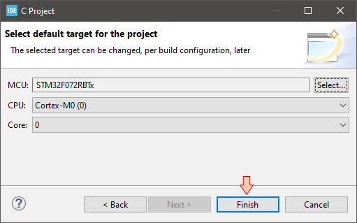
Review the MCU settings, then click Finish.
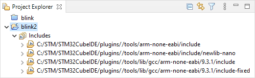
An empty "blink2" project is created and added to your workspace. Because MCU ARM GCC toolchain was selected, a set of include paths are predefined for the C standard libraries:
Right-Click on the ![]() folder and select New→
folder and select New→ ![]() Source File.
Source File.
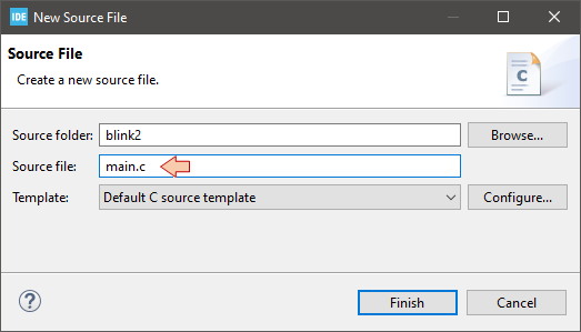
In the New Source File dialog, name the file "main.c" and then click Finish.
Again, Right-Click on the ![]() folder and select New→
folder and select New→ ![]() Other.
Other.
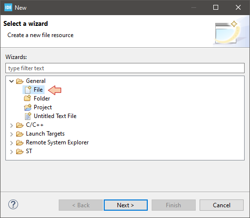
In the New dialog, select ![]() File from the General category.
File from the General category.
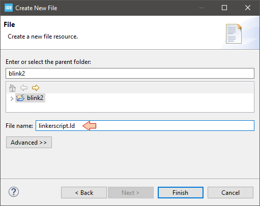
Then, in the Create New File dialog, name the file "linkerscript.ld" and then click Finish.
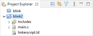
Now, the project structure should be:
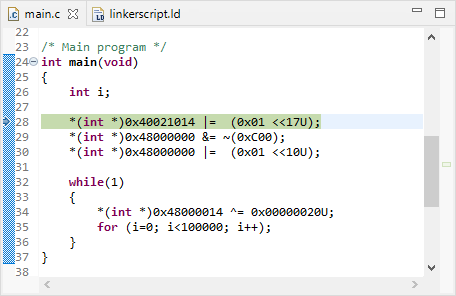
Double-Click the main.c file and copy/paste the code below:
/*
 * main.c
 *
 *  Created on: May 1, 2021
 *      Author: Laurent
 */

void   reset_handler        (void);
void   default_handler      (void);
int    main                 (void);

/* Minimal vector table */
__attribute__ ((section(".isr_vector")))

void (* const interrupt_vector_table[])(void) =
{
	(void *)0x20000800, 	// 0 - stack
	reset_handler, 	 	// 1 - reset handler
	default_handler, 	// 2 - NMI handler
	default_handler, 	// 3 - Hardfault handler
};

/* Main program */
int main(void)
{
    int i;

    *(int *)0x40021014 |=  (0x01 <<17U);
    *(int *)0x48000000 &= ~(0xC00);
    *(int *)0x48000000 |=  (0x01 <<10U);

    while(1)
    {
    	*(int *)0x48000014 ^= 0x00000020U;
    	for (i=0; i<100000; i++);
    }
}

/* Reset handler */
void reset_handler (void)
{
    main();
}

/* Default handler */
void default_handler(void)
{
    while(1);
}
Double-Click the linkerscript.ld file and copy/paste the code below:
/*	Minimal LinkerScript */

/* Entry Point */

ENTRY(reset_handler)

/* Specify the memory areas */

MEMORY
{
FLASH (rx)      : ORIGIN = 0x08000000, LENGTH = 128K
RAM (xrw)      	: ORIGIN = 0x20000000, LENGTH = 16K
}

/* Define output sections */

SECTIONS
{
  /* The startup code goes first into FLASH */
  .isr_vector :
  {
    . = ALIGN(4);
    KEEP(*(.isr_vector)) 	/* Startup code */
    . = ALIGN(4);
  } >FLASH

  /* The program code and other data goes into FLASH */
  .text :
  {
    . = ALIGN(4);
    *(.text)           		/* .text  sections (code) */
    *(.text*)          		/* .text* sections (code) */
    *(.glue_7)         		/* glue arm to thumb code */
    *(.glue_7t)        		/* glue thumb to arm code */
    *(.eh_frame)

    KEEP (*(.init))
    KEEP (*(.fini))

    . = ALIGN(4);
    _etext = .;        /* define a global symbols at end of code */
  } >FLASH

  /* Constant data goes into FLASH */
  .rodata :
  {
    . = ALIGN(4);
    *(.rodata)         /* .rodata sections (constants, strings, etc.) */
    *(.rodata*)        /* .rodata* sections (constants, strings, etc.) */
    . = ALIGN(4);
  } >FLASH


  /* Initialized data sections goes into RAM, load LMA copy after code */
  .data :
  {
    . = ALIGN(4);
    _sdata = .;        /* create a global symbol at data start */
    *(.data)           /* .data sections */
    *(.data*)          /* .data* sections */

    . = ALIGN(4);
    _edata = .;        /* define a global symbol at data end */
  } >RAM AT> FLASH


  /* Uninitialized data section into "RAM" Ram type memory */
  . = ALIGN(4);
  .bss :
  {
    /* This is used by the startup in order to initialize the .bss section */
    _sbss = .;         /* define a global symbol at bss start */
    __bss_start__ = _sbss;
    *(.bss)
    *(.bss*)
    *(COMMON)

    . = ALIGN(4);
    _ebss = .;         /* define a global symbol at bss end */
    __bss_end__ = _ebss;
  } >RAM
}
Then save all files ![]() .
.
At this moment, you've just re-create the "Mr Robot" blink example within STM32CubeIDE. Let us now configure the build process.
2. Build Configuration
Right-Click on the ![]() folder and select Properties.
folder and select Properties.
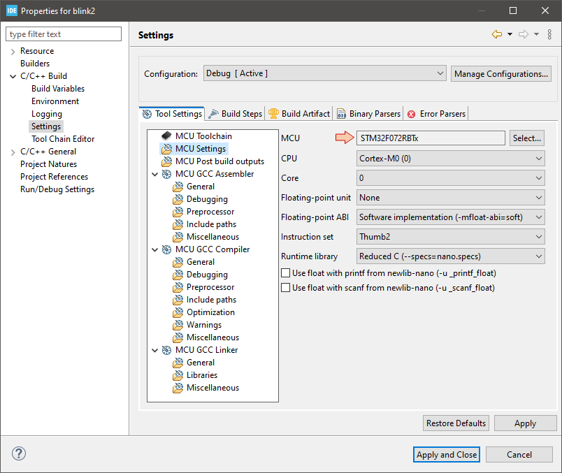
In the left tree view, select the C/C++ Build category, and then the Settings subcategory. In the Settings options, select the Tool Settings tab, and then the MCU Settings folder.
Review the MCU Settings. If for any reason your target is not there (STM32F072RBTx), you may click the Select... button from the MCU field to pick-up your target part number.
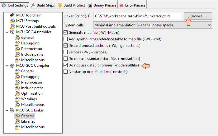
Next, you need to set the linker options. Still in the Settings subcategory, select MCU GCC Linker\General folder and edit the Linker Script field to match the file name of your linker script file. You can also click the Browse... button and navigate to your linkerscript.ld file.
Also check the Do not use default libraries option. Not doing so produces warnings at build time, as the linker looks for system-level functions that are not relevant here.
When your done, you can Apply and Close the whole project properties.
3. Build the Project
With the ![]() folder being selected, click the
folder being selected, click the ![]() Build button and watch the Console area:
Build button and watch the Console area:
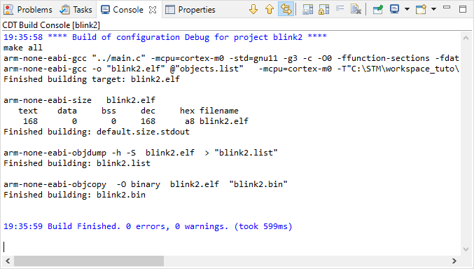
This window reports build (i.e. compile and link) process execution. As you can observe, that's pretty much the same process as the one you executed manually previously.
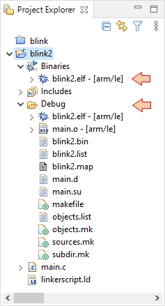
There should be no errors or warnings. Note that project structure has been populated with new items:
A Binaries section
A Debug folder that contains all the files generated during the build process (including the blink.elf binary file)
4. Configure the debug session
This part is a recall of something you already done in the Hello World #1 tutorial. The steps are just the same.
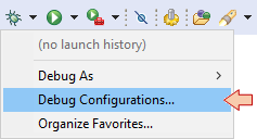
In the main toolbar, click the dropdown arrow besides the debug button ![]() and select Debug Configurations...:
and select Debug Configurations...:
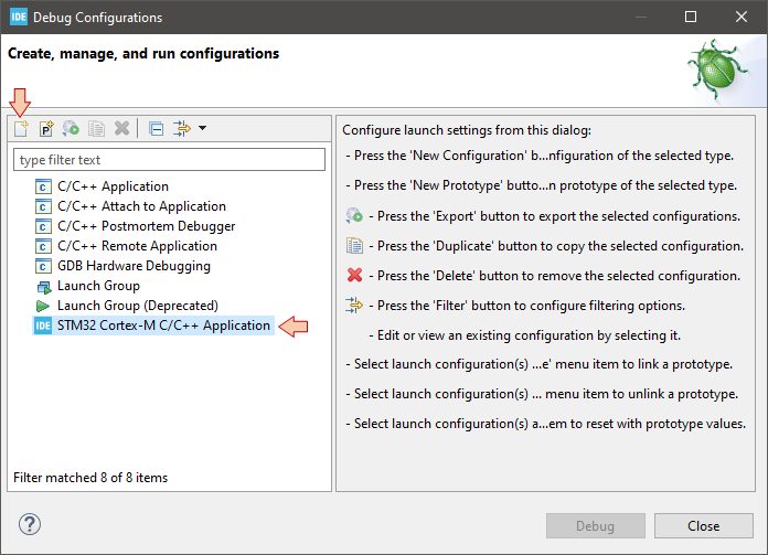
In the Debug Configuration dialog, select STM32 Cortex-M C/C++ Application, and then the New launch configuration button ![]() :
:
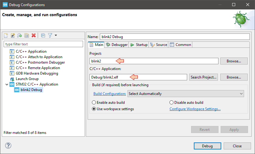
Make sure the new configuration has been created and review parameters in the Main tab:
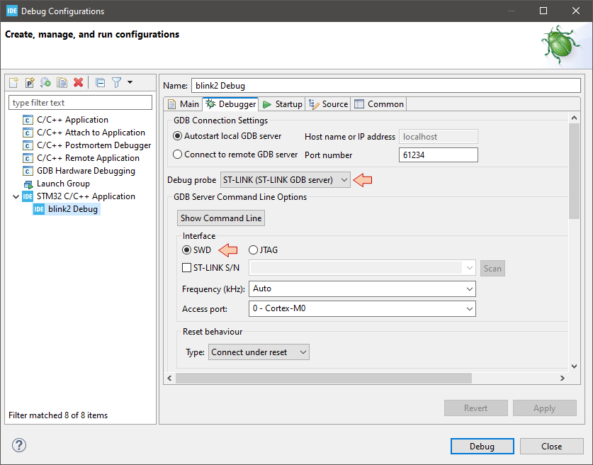
Then move to the Debugger tab and make sure that Debug probe is ST-LINK with SWD Interface:
When you've made sure that everything is set, then you can just close the Debug Configurations dialog.
Now, you can either just run ![]() the application on the target, or enter a debug
the application on the target, or enter a debug ![]() session.
session.
5. Run the application
Make sure your Nucleo board is connected, then click the Run button ![]() and watch the STM32CubeIDE console. As you can see, the whole process includes:
and watch the STM32CubeIDE console. As you can see, the whole process includes:
Stating a debug session (gdb).
Downloading (flashing) the program into the target MCU by calling STM32CubeProgrammer, just like you did manually in the Hello World #2 tutorial.
Closing the debug session.
STMicroelectronics ST-LINK GDB server. Version 5.8.0
Copyright (c) 2020, STMicroelectronics. All rights reserved.

Starting server with the following options:
        Persistent Mode            : Disabled
        Logging Level              : 1
        Listen Port Number         : 61234
        Status Refresh Delay       : 15s
        Verbose Mode               : Disabled
        SWD Debug                  : Enabled
        InitWhile                  : Enabled

Waiting for debugger connection...
Debugger connected
-------------------------------------------------------------------
                                STM32CubeProgrammer v2.7.0-RC1
-------------------------------------------------------------------
ST-LINK SN  : 066FFF535353897167055745
ST-LINK FW  : V2J37M27
Board       : NUCLEO-F072RB
Voltage     : 3.26V
SWD freq    : 4000 KHz
Connect mode: Under Reset
Reset mode  : Hardware reset
Device ID   : 0x448
Revision ID : Rev Z
Device name : STM32F07x
Flash size  : 128 KBytes
Device type : MCU
Device CPU  : Cortex-M0

Memory Programming ...
Opening and parsing file: ST-LINK_GDB_server_a06060.srec
  File          : ST-LINK_GDB_server_a06060.srec
  Size          : 168 Bytes
  Address       : 0x08000000

Erasing memory corresponding to segment 0:
Erasing internal memory sector 0
Download in Progress:

File download complete
Time elapsed during download operation: 00:00:00.110

Verifying ...

Download verified successfully

Debugger connection lost.
Shutting down...
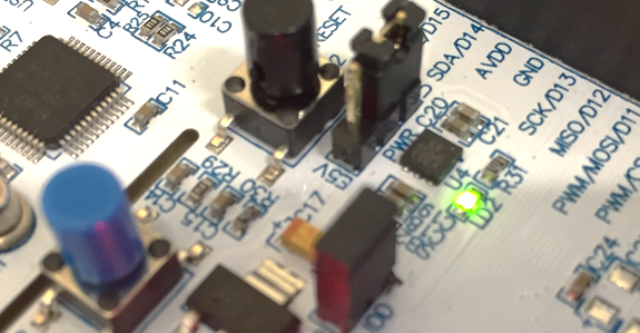
Watch the Nucleo board, you should get the LED blinking:
6. Debug the application
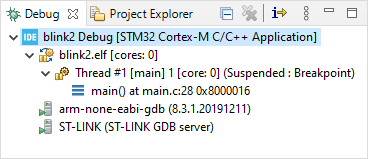
Click the ![]() debug button and watch the console to make sure there's no reported problems. After a little while you should enter the debugger session:
debug button and watch the console to make sure there's no reported problems. After a little while you should enter the debugger session:
From there, you can control program execution using usual toolbar commands (![]() ,
, ![]() ,
, ![]() ,
, ![]() ,
, ![]() ,
, ![]() , ...).Run the program full-speed by clicking the Resume button
, ...).Run the program full-speed by clicking the Resume button ![]() . You should get the blinking LED as expected.
. You should get the blinking LED as expected.
Note that a debug session runs few processes in the background of your computer. These processes are listed in the Debug frame and include:
The gdb debugger itself, from the MCU ARM GCC toolchain
The ST-Link gdb server for specific access to the Nucleo hardware
When you're done debugging, that very important that you leave the debugger clean, and these process should terminate automatically. Suspend the debugger ![]() and terminate
and terminate ![]() the debug session and switch back to C/C++ perspective.
the debug session and switch back to C/C++ perspective.
7. About perspectives
STM32CubeIDE prompts you when a perspective change is advised depending on the action you trig. Remember that a Perspective in Eclipse is nothing more that an arrangement of frames.
So far, we've used 3 different perspectives :
The development perspective is used for project management, code editing and building projects
The debugger perspective is used for debug sessions
The MX perspective, used in tutorial Hello World #1, is for graphical configuration using CubeMX.
You can actually switch Perspective at any time using these toolbar shortcuts:![]()
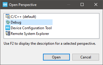
Click the Open Perspective ![]() button, and select the Debug perspective (or simply click the Debug Perspective
button, and select the Debug perspective (or simply click the Debug Perspective ![]() button in that toolbar), and switch back to the debug perspective. Note that doing this does not start a debug session, and that's exactly want we want.
button in that toolbar), and switch back to the debug perspective. Note that doing this does not start a debug session, and that's exactly want we want.
8. Killing debug processes
In the debugger perspective, you can then make sure that all debug processes have been terminated with no problem: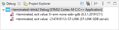
There are several reason for the debugger to not close cleanly:
A crash of your application can accidentally break to communication between the Nucleo board and gdb.
You removed the USB cable while debugging.
Your application enters a deep low-power mode, which also breaks the communication.
...
When that happens, you might need to terminate (kill) debug processes manually, using these contextual menu entries:
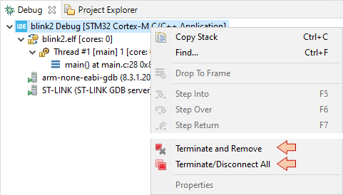
If the debug session is not cleaned after exit, you'll not ba able to start a new one...
9. Summary
In this tutorial, you've learned how to create and configure a new empty project, free from any STM32 libraries, within STM32CubeIDE. Again we've used the "Mr Robot" code example to get the LED blinking with only one short source file.
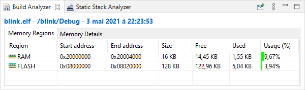
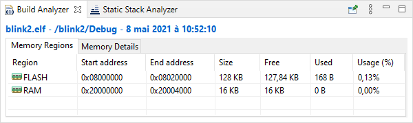
Just for fun, let us compare the memory footprint of both Hello World projects, from either the Cube (blink) or the Mr Robot (blink2) approaches. Remember that the two projects basically perform the very same thing... blinking a LED...
With Cube, the project filled 5kB of FLASH memory and requires 1.5kB of RAM (10% of the total available) for static variables.
While with no libraries, the project filled only 168B of FLASH, and does not require any RAM for static variables. That is a huge difference...
Well, that comparison is not really fair...
The Cube/HAL workflow involves many source files whereas only one short main.c with no library inclusion does the same. Why is that ?
On one hand, HAL libraries have been developed with portability across all the STM32 family range in mind. It means that code written for a specific STM32_XX target can be ported to another STM32_YY target with minimal effort. The price to pay is an additional hardware abstraction layer that involves more code. Yet these libraries are not 100% bug free, and fine tuning of the peripherals is not always supported. But to me, the major drawback of using these libraries is the hardware abstraction paradigm itself. You MUST understand the hardware if you want to be a good embedded developer and address complex situations, develop your own drivers, or fine tune power consumption. The Reference Manual is your best (and only) friend here.
On the other hand, the quite extreme above example is not totally honest because some very important stuff is missing, as you will see in the next tutorials. For instance, the use of magic numbers (i.e. explicit register addresses, masks, constants, ...) is something you should absolutely avoid for code maintainability. Do you actually understand what this code is doing ? I guess no, and that is normal because the writing is way too much esoteric.
So we need something in between. That "something" is called the CMSIS layer (Common Micro-controller Software Interface Standard). It consists of a reduced set of source files that you include into your project structure to make life easier without any further abstraction. It is time to move to the next tutorial.
- Log in to post comments