2.1. GPIOs
1. Introduction
This tutorial is dedicated to the implementation of few BSP functions. In the world of embedded systems, BSP stands for “Board Support Package”. In simple words, it is a collection of low-level functions to address on-board components such as I/Os, displays, sensors, communication interfaces… A collection of functions that simplifies the software interface with a given peripheral is also called a library, or a driver.
Nucleo boards are rather poor in terms of accessories. Basically, you have a user LED, a user button, and a serial interface through the ST-Link dongle. LEDs and Buttons are directly interfaced with MCU pins in either output or input mode. These are configured by means of GPIO (General Purpose Input Output) peripherals.
2. Starting project and first commit
Start STM32CubeIDE and open my_project project. At this step, my_project is a rather clean starting project you've created by cloning blink3 project. my_project project will be used all along subsequent tutorials.
We will start by some housework to get a clean starting point. In the main() function, remove the LED blinking code. In the SystemClock_Config(), we don't need the MCO on PA8 anymore as it was there only to monitor clock frequency. When done, your main.c may look like this:
/*
 * main.c
 *
 *  Created on: 24 mai 2021
 *      Author: Laurent
 */

#include "stm32f0xx.h"

// Static functions
static void SystemClock_Config (void);

// Main function
int main()
{
	// Configure System Clock
	SystemClock_Config();

	// Do nothing
	while(1)
	{
	}
}

/*
 * Clock configuration for the Nucleo STM32F072RB board
 * HSE input Bypass Mode            -> 8MHz
 * SYSCLK, AHB, APB1                -> 48MHz
 * PA8 as MCO with /16 prescaler    -> 3MHz
 */

static void SystemClock_Config()
{
	uint32_t	HSE_Status;
	uint32_t	PLL_Status;
	uint32_t	SW_Status;
	uint32_t	timeout = 0;
	timeout = 1000000;

	// Start HSE in Bypass Mode
	RCC->CR |= RCC_CR_HSEBYP;
	RCC->CR |= RCC_CR_HSEON;

	// Wait until HSE is ready
	do
	{
		HSE_Status = RCC->CR & RCC_CR_HSERDY_Msk;
		timeout--;
	} while ((HSE_Status == 0) && (timeout > 0));

	// Select HSE as PLL input source
	RCC->CFGR &= ~RCC_CFGR_PLLSRC_Msk;
	RCC->CFGR |= (0x02 <<RCC_CFGR_PLLSRC_Pos);

	// Set PLL PREDIV to /1
	RCC->CFGR2 = 0x00000000;

	// Set PLL MUL to x6
	RCC->CFGR &= ~RCC_CFGR_PLLMUL_Msk;
	RCC->CFGR |= (0x04 <<RCC_CFGR_PLLMUL_Pos);

	// Enable the main PLL
	RCC-> CR |= RCC_CR_PLLON;
	// Wait until PLL is ready
	do
	{
		PLL_Status = RCC->CR & RCC_CR_PLLRDY_Msk;
		timeout--;
	} while ((PLL_Status == 0) && (timeout > 0));

	// Set AHB prescaler to /1
	RCC->CFGR &= ~RCC_CFGR_HPRE_Msk;
	RCC->CFGR |= RCC_CFGR_HPRE_DIV1;

	//Set APB1 prescaler to /1
	RCC->CFGR &= ~RCC_CFGR_PPRE_Msk;
	RCC->CFGR |= RCC_CFGR_PPRE_DIV1;

	// Enable FLASH Prefetch Buffer and set Flash Latency
	FLASH->ACR = FLASH_ACR_PRFTBE | FLASH_ACR_LATENCY;

	// Select the main PLL as system clock source
	RCC->CFGR &= ~RCC_CFGR_SW;
	RCC->CFGR |= RCC_CFGR_SW_PLL;

	// Wait until PLL becomes main switch input
	do
	{
		SW_Status = (RCC->CFGR & RCC_CFGR_SWS_Msk);
		timeout--;
	} while ((SW_Status != RCC_CFGR_SWS_PLL) && (timeout > 0));

	// Update SystemCoreClock global variable
	SystemCoreClockUpdate();
}
Save all ![]() , build
, build ![]() and make sure there is no error or warning.
and make sure there is no error or warning.
Create if needed, setup a debug configuration and start a debug session ![]() to make sure everything works fine. Step over
to make sure everything works fine. Step over ![]() the SystemClock_Config() function and check whether the SystemCoreClock global variable changes from 8MHz to 48MHz, then terminate
the SystemClock_Config() function and check whether the SystemCoreClock global variable changes from 8MHz to 48MHz, then terminate ![]() .
.
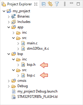
To begin, create a new ![]() source file bsp.c under bsp/src folder, and a new
source file bsp.c under bsp/src folder, and a new ![]() header file bsp.h under bsp/inc folder:
header file bsp.h under bsp/inc folder:

At this point, you are ready to start the Git history that will be used to evaluate your progress. Using the instructions provided before:
- Create a local repository for my_project.
- Configure the remote repository. You must use the GitLab project the teacher has created for you. It is named after you firstname.lastname and located in the eval_tutos_MEA3 group.
- Make sure language translation is not engaged in your navigator...
 | - - |
3. LED driver
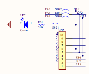
A look at the board schematics tells us that the green user LED is connected to the pin PA5 of the MCU. Given that LED cathode goes to ground, the LED is "ON" when PA5 is at its high logic voltage.

Let us take a moment to think about what functions we would like to have in order to play with the LED:
- A function that turn the LED on
- A function that turn the LED off
- A function that toggle the LED state
There is no need for any argument (there’s only one LED), and these functions may return nothing. Note that it would have been possible to use a single function that sets the LED state using an argument (ON/OFF/Toggle). That's a matter of taste.
We know that a MCU pin needs to be configured to serve as an output. If we include the pin configuration into the previous functions, it will be done every time we want to change the LED state. This is a waste of both CPU time and power consumption as configuration does not change once it is done. Therefore, let us write a separate function to address pin configuration, that will be called only once at the beginning of the main code.
Open edit bsp.h and write the following function prototypes:
/*
 * bsp.h
 *
 *  Created on: 5 août 2017
 *      Author: Laurent
 */

#ifndef BSP_INC_BSP_H_
#define BSP_INC_BSP_H_

#include "stm32f0xx.h"

/*
 * LED driver functions
 */

void	BSP_LED_Init	(void);
void	BSP_LED_On	(void);
void	BSP_LED_Off	(void);
void	BSP_LED_Toggle	(void);

#endif /* BSP_INC_BSP_H_ */
Note that when creating new headers, Eclipse automatically protects code from recursive inclusion:
#ifndef HEADERNAME_H_
#define HEADERNAME_H_
...
#endif
It is strongly advised to keep it… Recursive inclusion corresponds to the situation below, that would produce an infinite inclusion loop during the build preprocess if not under the protection of the above directives:
| |
Open bsp.c for edit and start the implementation of functions. Adopt a clear strategy in the function and variable naming. That’s VERY important when code grows.
In the following, the function belongs to the BSP, concerns the LED, and its purpose is the initialization of the MCU pin. Let’s name the function BSP_LED_Init():
/*
 * bsp.c
 *
 *  Created on: 5 août 2017
 *      Author: Laurent
 */

#include "bsp.h"

/*
 * BSP_LED_Init()
 * Initialize LED pin (PA5) as a High-Speed Push-Pull output
 * Set LED initial state to OFF
 */

void BSP_LED_Init()
{
	// Enable GPIOA clock
	RCC->AHBENR |= RCC_AHBENR_GPIOAEN;

	// Configure PA5 as output
	GPIOA->MODER &= ~GPIO_MODER_MODER5_Msk;
	GPIOA->MODER |= (0x01 <<GPIO_MODER_MODER5_Pos);

	// Configure PA5 as Push-Pull output
	GPIOA->OTYPER &= ~GPIO_OTYPER_OT_5;

	// Configure PA5 as High-Speed Output
	GPIOA->OSPEEDR &= ~GPIO_OSPEEDR_OSPEEDR5_Msk;
	GPIOA->OSPEEDR |= (0x03 <<GPIO_OSPEEDR_OSPEEDR5_Pos);

	// Disable PA5 Pull-up/Pull-down
	GPIOA->PUPDR &= ~GPIO_PUPDR_PUPDR5_Msk;

	// Set Initial State OFF
	GPIOA->BSRR |= GPIO_BSRR_BR_5;
}
You must refer to the reference manual for a complete description of RCC AHBENR register, and GPIO MODER, OTYPER, OSPEEDR, PUPDR, BSRR registers.
Next comes the three controlling functions:
/*
 * BSP_LED_On()
 * Turn ON LED on PA5
 */

void BSP_LED_On()
{
	GPIOA->BSRR = GPIO_BSRR_BS_5;
}

/*
 * BSP_LED_Off()
 * Turn OFF LED on PA5
 */

void BSP_LED_Off()
{
	GPIOA->BSRR = GPIO_BSRR_BR_5;
}

/*
 * BSP_LED_Toggle()
 * Toggle LED on PA5
 */

void BSP_LED_Toggle()
{
	GPIOA->ODR ^= GPIO_ODR_5;
}
That’s it. You’ve written a LED driver. Not too hard?
Test the LED functions in the main code. The example below must be used with the debugger stepping mode, otherwise the state change is too fast to be seen (unless you probe PA5 with an oscilloscope).
/*
 * main.c
 *
 *  Created on: 5 août 2017
 *      Author: Laurent
 */

#include "stm32f0xx.h"
#include "bsp.h"

// Static functions
static void SystemClock_Config(void);

// Main function
int main()
{
	// Configure System Clock
	SystemClock_Config();

	// Initialize LED pin
	BSP_LED_Init();

	// Turn LED On
	BSP_LED_On();

	// Turn LED Off
	BSP_LED_Off();

	while(1)
	{
		// Toggle LED state
		BSP_LED_Toggle();
	}
}

// ...
 | - - |
4. Push-button driver
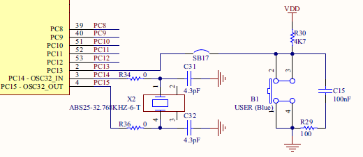
Again, we start with the board schematics. The user button is a switch that connects PC13 pin to ground when pushed down. Otherwise, PC13 pin is held at high logic level by means of the pull-up resistor R30.

In order to interface the push-button, we will write two functions:
- A function to initialize PC13 as an input pin
- A function that return the state of the button (0 for released, 1 for pushed)
You can add those functions prototype in bsp.h, below LED functions.
/*
 * Push-Button driver functions
 */

void       BSP_PB_Init		(void);
uint8_t    BSP_PB_GetState	(void);
Edit the functions implementation in bsp.c:
/*
 * BSP_PB_Init()
 * Initialize Push-Button pin (PC13) as input without Pull-up/Pull-down
 */

void BSP_PB_Init()
{
	// Enable GPIOC clock
	RCC->AHBENR |= RCC_AHBENR_GPIOCEN;

	// Configure PC13 as input
	GPIOC->MODER &= ~GPIO_MODER_MODER13_Msk;
	GPIOC->MODER |= (0x00 <<GPIO_MODER_MODER13_Pos);

	// Disable PC13 Pull-up/Pull-down
	GPIOC->PUPDR &= ~GPIO_PUPDR_PUPDR13_Msk;
}

/*
 * BSP_PB_GetState()
 * Returns the state of the button (0=released, 1=pressed)
 */

uint8_t BSP_PB_GetState()
{
	uint8_t state;
	if ((GPIOC->IDR & GPIO_IDR_13) == GPIO_IDR_13)
	{
		state = 0;
	}
	else
	{
		state = 1;
	}
	return state;
}
Then, test your new functions in main.c:
/*
 * main.c
 *
 *  Created on: 5 août 2017
 *      Author: Laurent
 */

#include "stm32f0xx.h"
#include "bsp.h"

// Static functions
static void SystemClock_Config(void);

// Main function
int main()
{
	// Configure System Clock
	SystemClock_Config();

	// Initialize LED pin
	BSP_LED_Init();

	// Initialize User-Button pin
	BSP_PB_Init();

	// Turn LED On
	BSP_LED_On();

	// Turn LED Off
	BSP_LED_Off();

	while(1)
	{
		// Turn LED On if User-Button is pushed down
		if (BSP_PB_GetState() == 1)
		{
			BSP_LED_On();
		}
		// Otherwise turn LED Off
		else
		{
			BSP_LED_Off();
		}
	}
}

// ...
The LED is ON only when you press the user-button.
 | - - |
4. Summary
In this tutorial, we have written simple drivers for both LED and user-button. Associated functions manipulate GPIOs with both input and output configurations.
- Log in to post comments
