
2.4. Timers
1. Software counting delays
In the first part of this tutorial, we will implement a naive delay function based on a software counting loop.
1.1. Delay implementation
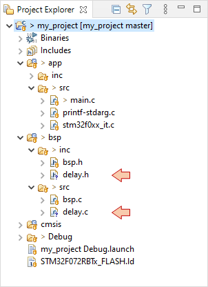
Open my_project and add a new source file delay.c and a new header file delay.h in your bsp folder:
Say we want two delay functions: one for milliseconds range, one for microseconds range. Add the two prototypes into delay.h:
/*
 * delay.h
 *
 *  Created on: 6 août 2017
 *      Author: Laurent
 */

#ifndef BSP_INC_DELAY_H_
#define BSP_INC_DELAY_H_

#include "stm32f0xx.h"

/*
 * Software counting delays
 */

void BSP_DELAY_ms	(uint32_t delay);
void BSP_DELAY_us	(uint32_t delay);

#endif /* BSP_INC_DELAY_H_ */
Next comes the implementation in delay.c:
/*
* delay.c
*
* Created on: 6 août 2017
* Author: Laurent
*/
#include "delay.h"
/*
* Basic delay functions
*/
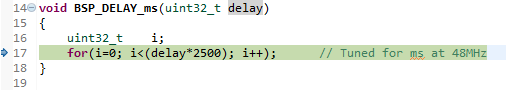
void BSP_DELAY_ms(uint32_t delay)
{
uint32_t i;
for(i=0; i<(delay*2500); i++); // Tuned for ms at 48MHz
}
void BSP_DELAY_us(uint32_t delay)
{
uint32_t i;
for(i=0; i<(delay*3); i++); // Tuned for µs at 48MHz
}
Note that both constants 2500 and 3 involved in the counting loops have been tuned by means of an oscilloscope to achieve expected delays. This tuning is only valid for the given clock settings (48MHz).
And finally, let us try something basic:
#include "stm32f0xx.h"
#include "bsp.h"
#include "delay.h"

// Static functions
static void SystemClock_Config(void);

// Main function
int main()
{
	// Configure System Clock
	SystemClock_Config();

	// Initialize LED pin
	BSP_LED_Init();

	// Main loop
	while(1)
	{
		BSP_LED_Toggle();
		BSP_DELAY_ms(500);
	}
}
Well, you should get a 1s period blinking LED. Fine!
 | - - |
1.2. Delay robustness
Let us take a closer look on what is really done when delay is called. Start a debug session and step ![]() over/
over/ ![]() into the code until you reach the beginning of the BSP_DELAY_ms() function:
into the code until you reach the beginning of the BSP_DELAY_ms() function:
Open the ![]() Disassembly view and you will see that the counting loop translates into 9 assembly lines to basically perform the required operations. We can see that there is a muls opcode in the loop so one can assume that the delay*2500 multiplication is repeated each time before the comparison is performed. Don’t you think this is stupid? You can make sure by
Disassembly view and you will see that the counting loop translates into 9 assembly lines to basically perform the required operations. We can see that there is a muls opcode in the loop so one can assume that the delay*2500 multiplication is repeated each time before the comparison is performed. Don’t you think this is stupid? You can make sure by ![]() stepping into assembly, but yes, it does!
stepping into assembly, but yes, it does!

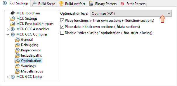
Terminate the debug session and open project Properties. In the C/C++ Build → Settings category open the Tool Settings → Optimization tab and set Optimization Level to -O1.
Apply and Close the Properties window.
Clean project (this is important, otherwise new optimization level is not applied), and then ![]() rebuild. Run
rebuild. Run ![]() the program and watch the LED. What do you see? It is blinking faster than before… Our delay is not robust against compiler optimization settings.
the program and watch the LED. What do you see? It is blinking faster than before… Our delay is not robust against compiler optimization settings.
Restart a debug ![]() session. Step until you reach the BSP_DELAY_ms() function again. Now look at disassembly. The same counting loop translate into 3 assembly lines only. The product 500*2500=1250000 is now stored into r0 once before looping. Smart!
session. Step until you reach the BSP_DELAY_ms() function again. Now look at disassembly. The same counting loop translate into 3 assembly lines only. The product 500*2500=1250000 is now stored into r0 once before looping. Smart!
Moreover, the variable i does not exist in memory anymore. Its value is directly held by r3 CPU register. Try to add &i in the Expressions view and you’ll get this:
Failed to execute MI command:
-data-evaluate-expression &i
Error message from debugger back end:
Address requested for identifier "i" which is in register $r3
Repeat above steps with -O2 optimization. If you step into assembly code, you will discover that the counting loop has been completely removed by the compiler… weird! What’s the need for a loop that does nothing after all…
The fact is that optimization level changes the way your C code translates into assembly code, making it more and more efficient as optimization level increases. Using optimization level different from –O0 needs special care as optimizer removes everything considered as “useless” (including operations and variables). Code that is useless to the optimizer is not always useless to you. A debug message for example, or intermediate variables can disappear. So, beware with optimizations, and it is always a good idea to start writing code with no optimizations. This way, you are sure to find what you expect from the debugger.
The purpose of the above experiment was to explain that timing based on software counting is very dependent on external parameters such as code optimization, or clock source/frequency. It is therefore advisable to implement delays with more robust approaches.
For now, come back to -O0 optimization level, clean and rebuild the project.
2. Timer as time-base
2.1. Simple time-base
There are up to 12 hardware timers available in the STM32F072 device. These timers are not all the same, as some of them boast larger counter width or other advanced features.
In order to setup a simple delay, let us pick-up a basic 16-bit timer with few features: TIM6
A timer is basically a counter (CNT). The counting speed is defined by both the bus clock frequency fclk and its 16-bit prescaler (PSC) value:
$$f_{counter}=\frac{f_{clk}}{PSC+1}$$
When the counter reaches a given value stored in its 16-bit Auto-Reload Register (ARR), it goes back to zero and generate an update event by setting its UIF flag to 1. The period between two successive update events is therefore:
$$T_{update}=\frac{ARR+1}{f_{counter}}$$
Let's say we want to implement a 1s delay with TIM6. TIM6 is connected to APB1 which runs at 48MHz.
- Setting PSC = (48000 -1) → we get a 1ms counting period
- Setting ARR = (1000 -1) → we get a 1s period between update events
Note that the solution is not unique. Setting PSC = (24000 -1) and ARR = (2000 -1) provides the same result. The difference is in the delay range/resolution you can achieve by adjusting the ARR value. The table below provides some working examples. Basically increasing the delay range implies a decrease in the delay tuning resolution.
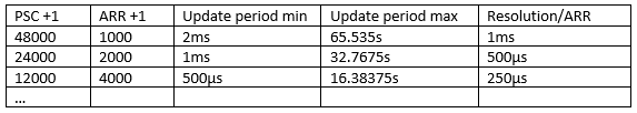
In summary, you must choose the PSC value (within 16-bit range) according to the resolution you want given that ARR must also fit into the 16-bit range.
Note that TIM2 is a 32-bit counter, if you need longer delay while keeping the resolution high enough.
First, add the following function implementation to bsp.c:
/*
 * BSP_TIMER_Timebase_Init()
 * TIM6 at 48MHz
 * Prescaler   = 48000 -> Counting period = 1ms
 * Auto-reload = 1000  -> Update period   = 1s
 */

void BSP_TIMER_Timebase_Init()
{
	// Enable TIM6 clock
	RCC->APB1ENR |= RCC_APB1ENR_TIM6EN;

	// Reset TIM6 configuration
	TIM6->CR1 = 0x0000;
	TIM6->CR2 = 0x0000;

	// Set TIM6 prescaler
	// Fck = 48MHz -> /48000 = 1KHz counting frequency
	TIM6->PSC = (uint16_t) 48000 -1;

	// Set TIM6 auto-reload register for 1s
	TIM6->ARR = (uint16_t) 1000 -1;

	// Enable auto-reload preload
	TIM6->CR1 |= TIM_CR1_ARPE;

	// Start TIM6 counter
	TIM6->CR1 |= TIM_CR1_CEN;
}
Then, add the function prototype to bsp.h:
/*
 * Timer functions
 */
void BSP_TIMER_Timebase_Init	(void);
Now, change the main() function into this simple code that continuously:
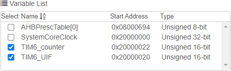
- puts the content of TIM6->CNT into a global variable TIM6_counter
- toggles global variable TIM6_UIF between 0 and 1024 every time UIF flag is set
// Global variables
uint16_t	TIM6_counter;
uint16_t	TIM6_UIF;

// Main function
int main()
{
	// Configure System Clock
	SystemClock_Config();

	// Initialize LED pin
	BSP_LED_Init();

	// Initialize and start time base
	BSP_TIMER_Timebase_Init();
	TIM6_UIF = 0;

	// Main loop
	while(1)
	{
		// Get current counter value
		TIM6_counter = TIM6->CNT;

		// If UIF is set
		if ((TIM6->SR & TIM_SR_UIF) == TIM_SR_UIF)
		{
			// Toggle TIM6_UIF between 0 and 1024
			TIM6_UIF ^= (0x01 <<10U);

			// Reset UIF
			TIM6->SR &= ~TIM_SR_UIF;
		}
	}
}
Build ![]() and run
and run ![]() the project.
the project.
Monitor both variables with STM32CubeMonitor:
You’ll get this:
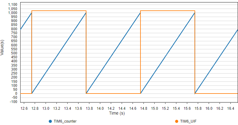
As expected, the counter keep counting from 0 to 1000 and then resets. Every time a reset occurs, the UIF flag is set. Period between UIF events is 1000ms. All is well.
2.2. Timer as a robust delay function
Let us write a new delay function based on TIM6. Add these prototypes to delay.h:
/*
 * Timer delays
 */

void BSP_DELAY_TIM_init		(void);
void BSP_DELAY_TIM_ms		(uint16_t ms);
Then add first function implementation in delay.c:
/*
 * timer_delay_init()
 * Initialize TIM6 with 1ms counting period
 * ARR is set to maximum value -> delay [2ms-65s]
 */

void BSP_DELAY_TIM_init(void)
{
	// Enable TIM6 clock
	RCC->APB1ENR |= RCC_APB1ENR_TIM6EN;

	// Reset TIM6 configuration
	TIM6->CR1 = 0x0000;
	TIM6->CR2 = 0x0000;

	// Set TIM6 prescaler
	// Fck = 48MHz -> /48000 = 1KHz counting frequency
	TIM6->PSC = (uint16_t) 48000 -1;

	// Set ARR to maximum value
	TIM6->ARR = (uint16_t) 0xFFFF;
}
This function basically only set the timer prescaler PSC in order to achieve a 1ms counting period. We are not going to use the update event, therefore ARR is set to maximum in order to allow full range counting (16-bit = 0 → 65535). The maximum possible delay is thus 65535ms.
The delay function is somehow plain. We’re just loop polling the counter register CNT until it reaches the desired waiting time:
/*
 * timer_delay_ms(uint16_t ms)
 * waits here for ms
 */
void BSP_DELAY_TIM_ms(uint16_t ms)
{
	// Resets TIM6 counter
	TIM6->EGR |= TIM_EGR_UG;

	// Start TIM6 counter
	TIM6->CR1 |= TIM_CR1_CEN;

	// Wait until TIM6 counter reaches delay
	while(TIM6->CNT < ms);

	// Stop TIM6 counter
	TIM6->CR1 &= ~TIM_CR1_CEN;
}
A quick check in main.c:
// Main function
int main()
{
	// Configure System Clock
	SystemClock_Config();

	// Initialize LED pin
	BSP_LED_Init();

	// Initialize Timer for delays
	BSP_DELAY_TIM_init();

	while(1)
	{
		// Toggle LED
		BSP_LED_Toggle();

		// Wait for 200ms
		BSP_DELAY_TIM_ms(200);
	}
}
Save all ![]() , build
, build ![]() and run
and run ![]() .
.
Then change optimization to -O1. Clean all, build and run again. The delay is not changed by optimization level this time. That's really interesting because you can now optimize other parts of the code for faster execution, without compromising the delay function.
Come back to -O0 after this.
| - - |
3. Timer as input capture
Timers have associated channels you can use to measure or drive timing-based events on I/O pins.
- Input capture mode is used when you need to measure a delay
- Output compare mode is used when you need to drive a signal with precise timing
Let us first illustrate Input Capture mode. In the following example, we will measure the duration user button is pushed down.
3.1. Single edge capture
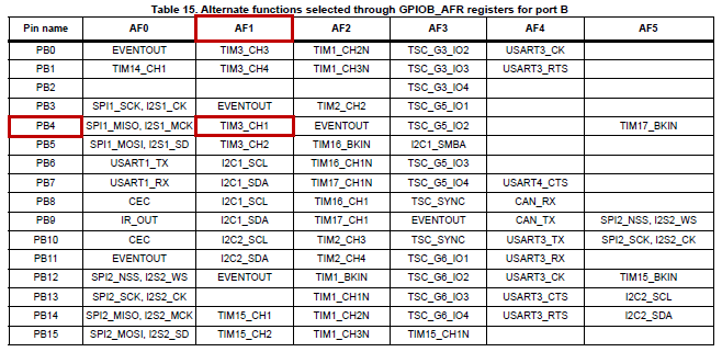
We need first to select an available timer, and a pin that we can use as timer channel. We can pick-up timer 3 (TIM3) and pin PB4 which corresponds to TIM3 Channel 1 when used in its Alternate Function 1 (AF1):
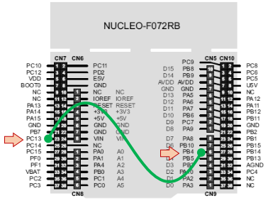
In order to connect the user button to PB4, you must fit a bond wire between PC13 and PB4. Doing so connects the user button to TIM3 Channel 1. Remember that PC13 is high when button is released, and low when button is pushed down.
 |  |
A function that initializes TIM3 to work as input capture of Channel 1 is given below. The function does the following
- Enable GPIOB clock and setup PB4 for AF1 (TIM3 Channel 1)
- Enable TIM3 clock
- Setup TIM3 prescaler according the timing resolution we want (1ms)
- Set the auto-reload value at maximum so that counter can reach 65535.
- Associate Channel 1 with trigger input 1 (PB4)
- Setup input capture on the falling edge of Channel 1
add this function to your bsp.c:
/*
 * BSP_TIMER_IC_Init()
 * TIM3 as Input Capture
 * Channel 1 -> PB4 (AF1)
 */

void BSP_TIMER_IC_Init()
{
	// Enable GPIOB clock
	RCC->AHBENR |= RCC_AHBENR_GPIOBEN;

	// Configure PB4 as Alternate function
	GPIOB->MODER &= ~(GPIO_MODER_MODER4_Msk);
	GPIOB->MODER |=  (0x02 <<GPIO_MODER_MODER4_Pos);

	// Set PB4 to AF1 (TIM3_CH1)
	GPIOB->AFR[0] &= ~(0x000F0000);
	GPIOB->AFR[0] |=  (0x00010000);

	// Enable TIM3 clock
	RCC -> APB1ENR |= RCC_APB1ENR_TIM3EN;

	// Reset TIM3 configuration
	TIM3->CR1  = 0x0000;
	TIM3->CR2  = 0x0000;
	TIM3->CCER = 0x0000;

	// Set TIM3 prescaler
	// Fck = 48MHz -> /48000 = 1KHz counting frequency
	TIM3->PSC = (uint16_t) 48000 -1;

	// Set Auto-Reload to maximum value
	TIM3->ARR = (uint16_t) 0xFFFF;

	// Reset Input Capture configuration
	TIM3->CCMR1 = 0x0000;
	TIM3->CCMR2 = 0x0000;

	// Set Channel 1 input on TI1
	TIM3->CCMR1 |= (0x01 <<TIM_CCMR1_CC1S_Pos);

	// Filter with N=8
	TIM3->CCMR1 |= (0x03 <<TIM_CCMR1_IC1F_Pos);

	// Select falling edge for channel 1
	TIM3->CCER |= (0x00 <<TIM_CCER_CC1NP_Pos) | (0x01 <<TIM_CCER_CC1P_Pos);

	// Enable capture on channel 1
	TIM3->CCER |= (0x01 <<TIM_CCER_CC1E_Pos);

	// Enable TIM3
	TIM3->CR1 |= TIM_CR1_CEN;
}
Add the prototype to bsp.h:
/*
 * Timer functions
 */

void BSP_TIMER_Timebase_Init	(void);
void BSP_TIMER_IC_Init		(void);
And now we can test something simple in main.c:
// Main function
int main()
{
	// Configure System Clock
	SystemClock_Config();

	// Initialize Console
	BSP_Console_Init();
	my_printf("Console Ready!\r\n");

	// Initialize Timer for delays
	BSP_DELAY_TIM_init();

	// Initialize Timer for Input Capture
	BSP_TIMER_IC_Init();

	while(1)
	{
		// Report TIM3 status (CNT and CCR1 registers)
		my_printf("CNT->%05d Fall->%05d\r", TIM3->CNT, TIM3->CCR1);

		// Wait for 100ms
		BSP_DELAY_TIM_ms(100);
	}
}
Console displays TIM3 counter value by polling its CNT register every 100ms. When you press the blue button, the current CNT value is saved in CCR1 register giving you the precise moment the falling edge occurs. This is the very basic functionality of Input Capture mode.
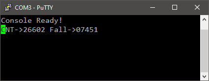
Note that there is no code in main() function to test the state of the button. Timer is doing everything by itself…
OK. If we want to measure the pulse duration, we also need to capture the rising event that occurs when button is released. Let us do that...
3.2. Dual edges capture
Edit the previous BSP_TIMER_IC_Init() function as follows:
...
	// Setup Input Capture
	TIM3->CCMR1 = 0x0000;
	TIM3->CCMR2 = 0x0000;

	// Channel 1 input on TI1
	TIM3->CCMR1 |= (0x01 <<TIM_CCMR1_CC1S_Pos);

	// Channel 2 input also on TI1
	TIM3->CCMR1 |= (0x02 <<TIM_CCMR1_CC2S_Pos);

	// Filter both channels with N=8
	TIM3->CCMR1 |= (0x03 <<TIM_CCMR1_IC1F_Pos) | (0x03 <<TIM_CCMR1_IC2F_Pos);

	// Select falling edge for channel 1
	TIM3->CCER |= (0x00 <<TIM_CCER_CC1NP_Pos) | (0x01 <<TIM_CCER_CC1P_Pos);

	// Select rising edge for channel 2
	TIM3->CCER |= (0x00 <<TIM_CCER_CC2NP_Pos) | (0x00 <<TIM_CCER_CC2P_Pos);

	// Enable capture on channel 1 & channel 2
	TIM3->CCER |= (0x01 <<TIM_CCER_CC1E_Pos) | (0x01 <<TIM_CCER_CC2E_Pos);

	// Enable TIM3
	TIM3->CR1 |= TIM_CR1_CEN;
...
We’ve enabled the timer Channel 2 as input capture. It is associated to the rising edge of trigger input 1 (PB4).
Let us now see what Channel 2 captures using this updated main() function:
// Main function
int main()
{
	// Configure System Clock
	SystemClock_Config();

	// Initialize Console
	BSP_Console_Init();
	my_printf("Console Ready!\r\n");

	// Initialize Timer for delays
	BSP_DELAY_TIM_init();

	// Initialize Timer for Input Capture
	BSP_TIMER_IC_Init();

	while(1)
	{
	   // Report TIM3 status (CNT, CCR1 and CCR2 registers)
	   my_printf("CNT->%05d Fall->%05d Rise->%05d\r", TIM3->CNT, TIM3->CCR1, TIM3->CCR2 );

	   // Wait for 100ms
	   BSP_DELAY_TIM_ms(100);
	}
}
Now, when you play with the blue button, you get a catch of CNT value for both falling and rising edges.
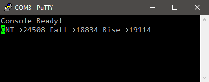
That is enough to compute the time the button is kept low. You can just perform the CCR2 – CCR1 time subtraction and get the pulse width. If you do so, you need to take care of the counter overflow (around 216).
Could we go further and free the CPU up from calculating the pulse width, and prevent counter overflow by the way? The answer is YES…
3.3. Dual edges capture with slave reset
The idea is to use the first (falling) edge to reset the timer counter. Doing so, the value caught in CCR2 would directly represent the pulse duration. And as long as the pulse is less that 65s, there is no risk of counter overflow.
Edit the previous BSP_TIMER_IC_Init() function as follows:
...
	// Setup Input Capture
	TIM3->CCMR1 = 0x0000;
	TIM3->CCMR2 = 0x0000;

	// Channel 1 input on TI1
	TIM3->CCMR1 |= (0x01 <<TIM_CCMR1_CC1S_Pos);

	// Channel 2 input also on TI1
	TIM3->CCMR1 |= (0x02 <<TIM_CCMR1_CC2S_Pos);

	// Filter with N=8
	TIM3->CCMR1 |= (0x03 <<TIM_CCMR1_IC1F_Pos) | (0x03 <<TIM_CCMR1_IC2F_Pos);

	// Select falling edge for channel 1
	TIM3->CCER |= (0x00 <<TIM_CCER_CC1NP_Pos) | (0x01 <<TIM_CCER_CC1P_Pos);

	// Select rising edge for channel 2
	TIM3->CCER |= (0x00 <<TIM_CCER_CC2NP_Pos) | (0x00 <<TIM_CCER_CC2P_Pos);

	// Enable capture on channel 1 & channel 2
	TIM3->CCER |= (0x01 <<TIM_CCER_CC1E_Pos) | (0x01 <<TIM_CCER_CC2E_Pos);

	// Choose Channel 1 as trigger input
	TIM3->SMCR |= (0x05 <<TIM_SMCR_TS_Pos);

	// Slave mode -> Resets counter when trigger occurs
	TIM3->SMCR |= (0x4 <<TIM_SMCR_SMS_Pos);

	// Enable TIM3
	TIM3->CR1 |= TIM_CR1_CEN;
...
Update main() function as CCR2 now holds the pulse length:
// Main function
int main()
{
	// Configure System Clock
	SystemClock_Config();

	// Initialize Console
	BSP_Console_Init();
	my_printf("Console Ready!\r\n");

	// Initialize Timer for delays
	BSP_DELAY_TIM_init();

	// Initialize Timer for Input Capture
	BSP_TIMER_IC_Init();

	while(1)
	{
	  // Report TIM3 status (CNT, CCR1 and CCR2 registers)
	  my_printf("CNT->%05d Start->%05d length->%05d\r", TIM3->CNT, TIM3->CCR1, TIM3->CCR2 );

	  // Wait for 100ms
	  BSP_DELAY_TIM_ms(100);
	}
}
Now, when you press the button:
- CCR1 holds the copy of current CNT value (start time)
- CNT resets to 0x0000
When you release the button:
- CCR2 holds a copy of current CNT (i.e. the time you’ve kept the button down)
If you have an oscilloscope at hand, probe PB4 and measure the time you keep the button pushed down. Compare with the length that the console reports. You should have a match within 1ms error.
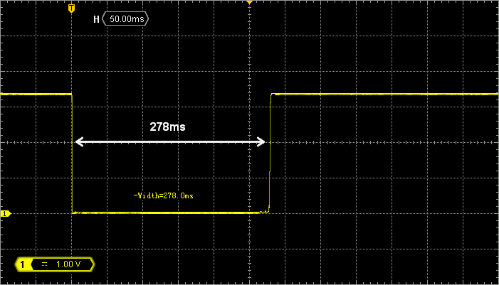

With these settings, the last pulse length is now always available in TIM3 CCR2 register, without any CPU intervention. You can use such timer configuration to convert a PWM signal into a data. This is very handy to read RC controller output (among other applications).
| - - |
4. Timer as output compare: PWM generation
4.1. What is a PWM signal?
Figure below shows an example of a PWM signal. PWM stands for “Pulse Width Modulation”. In short, you take a square signal and move along the time axis only one of his edges (it can be either the rising or the falling edge). Figure below illustrates a PWM signal with a moving falling edge. Only one edge is moving, therefore the period T of the PWM signal is constant. Moving one edge changes the duty cycle (w/T) in a range between 0% (when w=0) to 100% (when w=T).
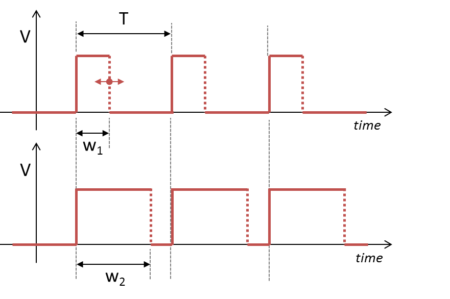
Timings of a digital PWM signal are defined by:
- Its period T (s)
- Its resolution (s). The resolution is the smallest possible change in the width w.
- Its duty cycle range (i.e. wmin, wmax).
Let us take an example: servomotors control.
4.2. Servomotors as practical example
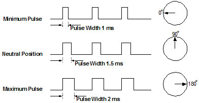
Servomotors are analog or digital devices converting input signal into an angular position of the wheel. Input signal is a pulse width ranging from 1ms to 2ms, with an arbitrary period (a common period for servomotors is 11ms).
When using 180° range servomotor, you get the left position (0°) with a 1ms pulse, a neutral position (90°)with a 1.5ms pulse and the right position (180°) with a 2ms pulse.
Now, say that we want to control the servomotor with at least 0.2° resolution. That means that we need about 180/0.2 = 900 discrete values for our pulse width. Let us round off this result to 1000 values.
4.3. Timer setup of PWM output
Say we want to simultaneously control 2 servomotors with one timer. We can pick up channels 1 and 2 of timer 1 (TIM1), mapped on pin PA8 and PA9 using their alternate function AF2.
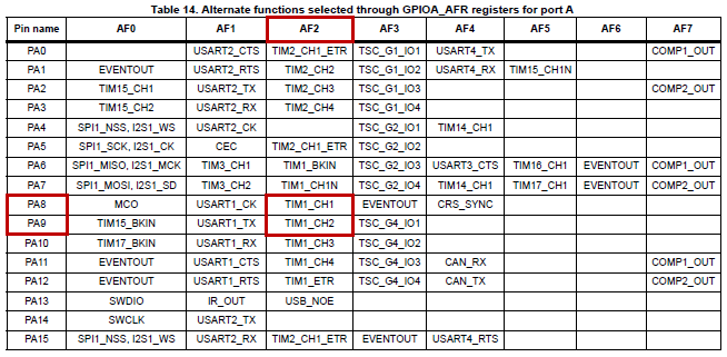
Note that PA8 is already in use in our project as MCO pin (3MHz Master Clock Output). We are not going to use MCO anyway, so let things be. The following configuration will override the PA8 function.
Our PWM specifications:
- A period T of 11ms
- A pulse width ranging from 1ms to 2ms
- A resolution corresponding to 1000 values between 1ms and 2ms = 1µs resolution
STM32 timers can be used to generate PWM signals by using the OC (Output Compare) feature. OC is a mechanism by which you can automatically generate events when the timer counter reaches chosen values.
Add the following function to bsp.c and associated prototype declaration to bsp.h.
/*
 * BSP_TIMER_PWM_Init()
 * TIM1 as Output Compare PWM mode
 * Channel 1 -> PA8 (AF2)
 * Channel 2 -> PA9 (AF2)
 */

void BSP_TIMER_PWM_Init()
{
	// Enable GPIOA clock
	RCC->AHBENR |= RCC_AHBENR_GPIOAEN;

	// Configure PA8 and PA9 as Alternate Function
	GPIOA->MODER &= ~(GPIO_MODER_MODER8_Msk | GPIO_MODER_MODER9_Msk);
	GPIOA->MODER |=  (0x02 <<GPIO_MODER_MODER8_Pos) | (0x02 <<GPIO_MODER_MODER9_Pos);

	// Set PA8 and PA9 to AF2 (TIM1)
	GPIOA->AFR[1] &= ~(0x000000FF);
	GPIOA->AFR[1] |=  (0x00000022);

	// Enable TIM1 clock
	RCC -> APB2ENR |= RCC_APB2ENR_TIM1EN;

	// Reset TIM1 configuration
	TIM1->CR1  = 0x0000;
	TIM1->CR2  = 0x0000;
	TIM1->CCER = 0x0000;

	// Set TIM1 prescaler
	// Fck = 48MHz -> /48 = 1MHz counting frequency (1µs resolution)
	TIM1->PSC = (uint16_t) 48 -1;

	// Set Auto-Reload to period = 11ms
	TIM1->ARR = (uint16_t) 11000;

	// Enable Auto-Reload Preload register
	TIM1->CR1 |= TIM_CR1_ARPE;

	// Setup Input Capture
	TIM1->CCMR1 = 0x0000;
	TIM1->CCMR2 = 0x0000;

	// Setup PWM mode 1 output
	TIM1->CCMR1 |= (0x06 <<TIM_CCMR1_OC1M_Pos) | TIM_CCMR1_OC1PE;
	TIM1->CCMR1 |= (0x06 <<TIM_CCMR1_OC2M_Pos) | TIM_CCMR1_OC2PE;

	// Set default PWM values
	TIM1->CCR1 = 1500;
	TIM1->CCR2 = 1500;

	// Enable Outputs
	TIM1->CCER |= TIM_CCER_CC1E | TIM_CCER_CC2E;

	// Enable Main output
	TIM1->BDTR |= TIM_BDTR_MOE;

	// Enable TIM1
	TIM1->CR1 |= TIM_CR1_CEN;
}
As soon as you call BSP_TIMER_PWM_Init() from the main() function, the timer start working as configured independently from the CPU activity. Try this and you’ll be sure:
// Main function
int main()
{
	// Configure System Clock
	SystemClock_Config();

	// Initialize Timer for PWM output
	BSP_TIMER_PWM_Init();

	while(1)
	{
           // CPU is doing nothing here, and forever...
	}
}
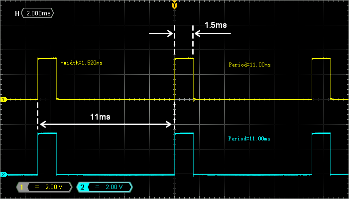
Probing PA8 and PA9 with an oscilloscope reveals the two PMW signals as expected. Period is 11ms and pulse width is 1.5ms.
Let us now write a small state machine to real-time module both pulse lengths between 1ms and 2ms (to mimic servomotor command):
// Main function
int main()
{
	uint16_t pulse_A, pulse_B;
	uint8_t	 state;

	// Configure System Clock
	SystemClock_Config();

	// Initialize Timer for delays
	BSP_DELAY_TIM_init();

	// Initialize Timer for PWM output
	BSP_TIMER_PWM_Init();

	// Initialize state variables
	state 	= 0;
	pulse_A = 1500;
	pulse_B = 1500;

	while(1)
	{
		// Set PWMs duty ratios according to pulse_A and pulse_B values
		TIM1->CCR1 = pulse_A;
		TIM1->CCR2 = pulse_B;
		// Manage state machine
		switch (state)
		{
			// Increasing A, Decreasing B
			case 0 :
			{
				pulse_A++;
				pulse_B--;
				// Stop condition -> State 1
				if (pulse_A == 2000) state = 1;
				break;
			}

			// Increasing B, Decreasing A
			case 1 :
			{
				pulse_A--;
				pulse_B++;
				// Stop condition -> State 0
				if (pulse_B == 2000) state = 0;
				break;
			}
		}

		// Wait for 2 ms
		BSP_DELAY_TIM_ms(2);
	}
}
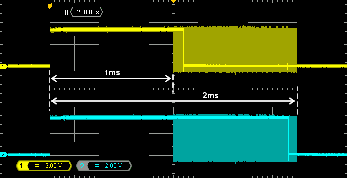
Observe the two PWM outputs on the oscilloscope. Figure below has been obtained by setting infinite persistence on the oscilloscope to reveal the time range of falling edges. Does the range of pulse widths match the servomotor input range?
| - - |
5. Summary
Timers are complex peripherals able to perform a variety of time-related tasks. This tutorial covered few applications including:
- Time base generation and simple delays implementation
- Input capture mode for measuring external pulse duration
- Output compare for PWM signal generation
- Log in to post comments