
3.4. UART RX DMA
1. Using the USART RX with DMA
1.1. Setting up the DMA to work with USART2
DMA stands for Direct Memory Access. The DMA controller is a specific peripheral you can consider as a small processor working in parallel to the main processor, and dedicated to the transfer of data between memory and peripherals (both ways) or even within the memory itself.
In this tutorial example, we will see how to configure the DMA controller and the USART2 peripheral so that USART incoming bytes are automatically stored in a memory buffer without having to interrupt the processor.
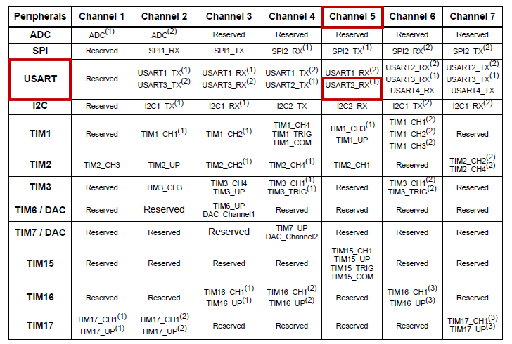
To understand the DMA organization, you need to open the STM32F0 Reference Manual and visit the DMA section. Table 3.1 provides a useful summary of available peripheral DMA requests, and on which DMA channels these requests are performed. One can see here that USART2_RX calls the DMA controller on its channel 5 or 6.
Let us use Channel 5 since no DMA remapping is required for this channel.
Configuring a DMA channel (i.e. routing) is not as complicated as it seems at first glance. DMA is in charge of taking data from a source address (memory or peripheral) and convey this data to a destination address (peripheral or memory). In addition the DMA needs to know whether the source or destination address is a buffer (i.e. an array of data) and the size (8/16/32) of the data to be conveyed. That’s almost it.
In our particular case:
At one end of the transfer (peripheral) is RDR register of USART2. It holds 8-bit data and its address is always the same, so we don’t want it to be incremented after each transfer
At the other end of the transfer (memory) is an array of 8-bit data defined as global variable rx_dma_buffer[8]. DMA must increment the destination address after each transfer in order to fill the buffer sequentially
The transfer direction is Peripheral → Memory
The amount of data to transfer is 8 bytes (corresponding to the size of the receiving buffer)
We want a circular filling of the memory (restart at the beginning when full)
In addition:
We can operate the DMA without any interruptions. You can disable the USART2 RXNE interruption (comment the concerned line)
You need to tell USART2 to call (request) for a DMA transfer each time a new byte is received
Edit the BSP_Console_Init() function in order to add a DMA functionality for incoming bytes (RX). Code is below:
/*
 * BSP_Console_Init()
 * USART2 @ 115200 Full Duplex
 * 1 start - 8-bit - 1 stop
 * TX -> PA2 (AF1)
 * RX -> PA3 (AF1)
 */

extern uint8_t rx_dma_buffer[8];
void BSP_Console_Init()
{
	// Enable GPIOA clock
	RCC->AHBENR |= RCC_AHBENR_GPIOAEN;
	// Configure PA2 and PA3 as Alternate function
	GPIOA->MODER &= ~(GPIO_MODER_MODER2_Msk | GPIO_MODER_MODER3_Msk);
	GPIOA->MODER |=  (0x02 <<GPIO_MODER_MODER2_Pos) | (0x02 <<GPIO_MODER_MODER3_Pos);
	// Set PA2 and PA3 to AF1 (USART2)
	GPIOA->AFR[0] &= ~(0x0000FF00);
	GPIOA->AFR[0] |=  (0x00001100);
	// Enable USART2 clock
	RCC -> APB1ENR |= RCC_APB1ENR_USART2EN;
	// Clear USART2 configuration (reset state)
	// 8-bit, 1 start, 1 stop, CTS/RTS disabled
	USART2->CR1 = 0x00000000;
	USART2->CR2 = 0x00000000;
	USART2->CR3 = 0x00000000;
	// Select PCLK (APB1) as clock source
	// PCLK -> 48 MHz
	RCC->CFGR3 &= ~RCC_CFGR3_USART2SW_Msk;
	// Baud Rate = 115200
	// With OVER8=0 and Fck=48MHz, USARTDIV =   48E6/115200 = 416.6666
	// BRR = 417 -> Actual BaudRate = 115107.9137 -> 0.08% error
	//
	// With OVER8=1 and Fck=48MHz, USARTDIV = 2*48E6/115200 = 833.3333
	// BRR = 833 -> Actual BaudRate = 115246.0984 -> 0.04% error (better choice)
	USART2->CR1 |= USART_CR1_OVER8;
	USART2->BRR = 833;
	// Enable both Transmitter and Receiver
	USART2->CR1 |= USART_CR1_TE | USART_CR1_RE;
	// Enable interrupt on RXNE event (disabled with DMA)
	// USART2->CR1 |= USART_CR1_RXNEIE;
	// Setup RX on DMA Channel 5
	// Start DMA clock
	RCC->AHBENR |= RCC_AHBENR_DMA1EN;
	// Reset DMA1 Channel 5 configuration
	DMA1_Channel5->CCR = 0x00000000;
	// Set direction Peripheral -> Memory
	DMA1_Channel5->CCR &= ~DMA_CCR_DIR;
	// Peripheral is USART2 RDR
	DMA1_Channel5->CPAR = (uint32_t)&USART2->RDR;
	// Peripheral data size is 8-bit (byte)
	DMA1_Channel5->CCR |= (0x00 <<DMA_CCR_PSIZE_Pos);
	// Disable auto-increment Peripheral address
	DMA1_Channel5->CCR &= ~DMA_CCR_PINC;
	// Memory is rx_dma_buffer
	DMA1_Channel5->CMAR = (uint32_t)rx_dma_buffer;
	// Memory data size is 8-bit (byte)
	DMA1_Channel5->CCR |= (0x00 <<DMA_CCR_MSIZE_Pos);
	// Enable auto-increment Memory address
	DMA1_Channel5->CCR |= DMA_CCR_MINC;
	// Set Memory Buffer size
	DMA1_Channel5->CNDTR = 8;
	// DMA mode is circular
	DMA1_Channel5->CCR |= DMA_CCR_CIRC;
	// Enable DMA1 Channel 5
	DMA1_Channel5->CCR |= DMA_CCR_EN;
	// Enable USART2 DMA Request on RX
	USART2->CR3 |= USART_CR3_DMAR;
	// Enable USART2
	USART2->CR1 |= USART_CR1_UE;
}
Note that since we have disabled the RXNE interrupt, you can also clean BSP_NVIC_Init() function:
	// Set priority level 1 for USART2 interrupt
	// NVIC_SetPriority(USART2_IRQn, 1);
	// Enable USART2 interrupts
	// NVIC_EnableIRQ(USART2_IRQn);
You can keep related ISR USART2_IRQHandler() but it will never be called.
1.2. Understanding DMA behavior
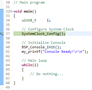
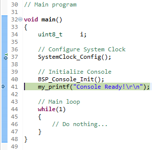
Now edit the main() function so that very little is done:
Declare rx_dma_buffer[8] global variable (keep previous global variables to avoid compiler error)
Call the BSP_Console_Init() function
Loop doing nothing
// Global variables
...
uint8_t rx_dma_buffer[8];
// Main function
int main()
{
// Configure System Clock
SystemClock_Config();
// Initialize Console
BSP_Console_Init();
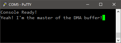
my_printf("Console Ready!\r\n");
// Main loop
while(1)
{
// Do nothing...
}
}
Save all ![]() , build the project
, build the project ![]() , open a serial terminal console and launch a debug session
, open a serial terminal console and launch a debug session ![]() .
.
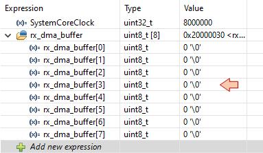
In the Expressions view ![]() , add 'rx_dma_buffer' variable, this is the buffer for incoming bytes
, add 'rx_dma_buffer' variable, this is the buffer for incoming bytes
For the moment, all is zero:
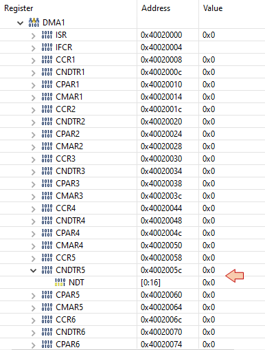
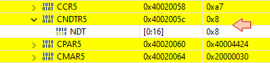
In the SFR view ![]() , unfold STM32F0x2→DMA1→CNDTR5 and watch NDT value. This is the DMA remaining transfer counter on Channel 5.
, unfold STM32F0x2→DMA1→CNDTR5 and watch NDT value. This is the DMA remaining transfer counter on Channel 5.
Then step over ![]() twice in order to execute the BSP_Console_Init() function:
twice in order to execute the BSP_Console_Init() function:
Now USART2 and DMA have been initialized. SFR view reports actual DMA counter:
Keep execution suspended (i.e. do not touch anything in the debugger) and bring the serial terminal (Putty)under focus.
Then hit the keyboard keys ‘a’, ‘z’, ‘e’, ‘r’, ‘t’, ‘y’. You will see nothing happen. It is normal.
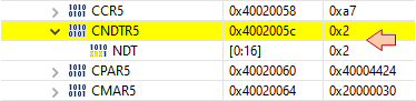
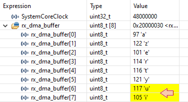
Come back to the debugger and step over next line ![]() . The welcome message is displayed in the console, but more interestingly: the keys you’ve hit before, while CPU was not running, are in the rx_dma_buffer!
. The welcome message is displayed in the console, but more interestingly: the keys you’ve hit before, while CPU was not running, are in the rx_dma_buffer!
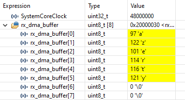
The DMA counter (CNDTR) is now 2. DMA counter works as a down-counter, holding the number of transfer left to be done.
So, what happened? After USART2 and DMA have been initialized, these peripherals become active independently from the CPU. Even with a suspended CPU (i.e. execution paused in debugger), the process of USART2 receiving data, then calling DMA to store bytes in the memory is active. When you’ve hit the keyboard in the serial terminal, the sent bytes have been transferred first to the USART2 RDR register. Then USART2 fired a DMA request and finally the DMA handled the data transfer to the memory. It was just necessary to step over once with the debugger to refresh the Expression view, but data was actually already there.
Hit two more keys ‘u’, ‘i’, in the terminal window (CPU still suspended). Then run/suspend (![]() /
/![]() ) the program to refresh the Expression and SFR views:
) the program to refresh the Expression and SFR views:
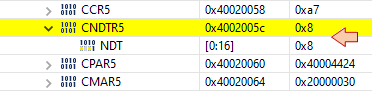
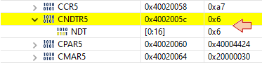
You can see that the two last bytes have been added into the array, and that DMA counter has been reset to initial count of 8. Hit two more keys ‘o’, ‘p’, in the terminal window. Then run/suspend again (![]() /
/![]() ) the program to refresh the Expression and SFR views:
) the program to refresh the Expression and SFR views:
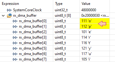
Because we've set the DMA to operate in Circular mode, the new bytes have been stored at the beginning of the buffer and DMA counter is now 6.
In summary:
No incoming byte is lost until the rx_dma_buffer[] is completely filled
When the rx_dma_buffer[] is fully filled (i.e. when DMA counter would reach 0), the DMA counter actually resets to its initial value (8) and new incoming bytes are stored again from the beginning of rx_dma_buffer[]. This is the circular mode behavior.
All these operations are performed without any help from the CPU. USART2, DMA and the Memory are working in total independence, even when CPU is stopped by the debugger.
 | - - |
2. Managing the receive buffer
2.1. Using polling and pointers
Let say we want a program that simply “echoes” the hit keys in the terminal console, making use of the DMA to handle USART RX Requests and a memory rx_dma_buffer[] allowing the task to be performed only once every second (i.e. leaving time for other tasks) without losing any incoming bytes.
A possible implementation would be this one:
// Main function
int main()
{
	uint8_t		DMA_Counter;
	uint8_t		index;
	// Configure System Clock
	SystemClock_Config();
	// Initialize Console
	BSP_Console_Init();
	my_printf("Console Ready!\r\n");
	// Initialize 1s timebase
	BSP_TIMER_Timebase_Init();
	BSP_NVIC_Init();
	// Initialize variables
	DMA_Counter = DMA1_Channel5->CNDTR;
	index = DMA_Counter;
	// Main loop
	while(1)
	{
		// Do every 1s
		if(timebase_irq == 1)
		{
			// Get actual DMA counter value
			DMA_Counter = DMA1_Channel5->CNDTR;
			// For all new received bytes
			while (index != DMA_Counter)
			{
				// Send byte to console
				while ( (USART2->ISR & USART_ISR_TC) != USART_ISR_TC);
				USART2->TDR = rx_dma_buffer[8-index];
				// Circular index update
				index--;
				if (index == 0) index = 8;
			}
			timebase_irq = 0;
		}
	}
}
Take some time to understand the code above. Basically, the index variable is used to address individual bytes in the rx_dma_buffer[] and is ‘running’ after the DMA counter.
You can test the program in the console. Type anything on the keyboard and you should see your input being updated every second without any loss… unless you hit more than 8 keys per second (which is not that hard)…
In this example, the main() function is polling the rx_dma_buffer[] every 1s. What would happen if you received more than 8 bytes per second?
Well, some bytes would be lost, overwritten by the DMA in the rx_dma_buffer[], before you found time to process (i.e. display) them.
Of course, you can deal with this issue by:
Increasing the buffer size
Making the polling period shorter
Note that by doing that, you will check the DMA state even in the case that no byte has been transferred…
An alternative is to rely on an additional feature of the DMA controller: DMA interrupts!
| - - |
2.2. Using DMA interrupts
The DMA controller is able to send interrupt signals based on several DMA events. One could for instance send an interrupt signal every time a byte is transferred from the USART to the Memory but this would be stupid since the whole purpose of the DMA being involved in the RX process is to avoid multiple interruptions of other important tasks.
When working with buffers, the DMA is able to trig two very useful events:
The Half-Transfer (HT) event, when DMA reaches the first half of the buffer
The Transfer-Complete (TC) event, when DMA reaches the end of the buffer and will start over at the beginning.
Edit the BSP_Console_Init() function and add the following setup:
...
	// Setup RX on DMA Channel 5
	// Start DMA clock
	RCC->AHBENR |= RCC_AHBENR_DMA1EN;
	// Reset DMA1 Channel 5 configuration
	DMA1_Channel5->CCR = 0x00000000;
	// Set direction Peripheral -> Memory
	DMA1_Channel5->CCR &= ~DMA_CCR_DIR;
	// Peripheral is USART2 RDR
	DMA1_Channel5->CPAR = (uint32_t)&USART2->RDR;
	// Peripheral data size is 8-bit (byte)
	DMA1_Channel5->CCR |= (0x00 <<DMA_CCR_PSIZE_Pos);
	// Disable auto-increment Peripheral address
	DMA1_Channel5->CCR &= ~DMA_CCR_PINC;
	// Memory is rx_dma_buffer
	DMA1_Channel5->CMAR = (uint32_t)rx_dma_buffer;
	// Memory data size is 8-bit (byte)
	DMA1_Channel5->CCR |= (0x00 <<DMA_CCR_MSIZE_Pos);
	// Enable auto-increment Memory address
	DMA1_Channel5->CCR |= DMA_CCR_MINC;
	// Set Memory Buffer size
	DMA1_Channel5->CNDTR = 8;
	// DMA mode is circular
	DMA1_Channel5->CCR |= DMA_CCR_CIRC;

	// Enable DMA HT & TC interrupts
	DMA1_Channel5->CCR |= DMA_CCR_HTIE | DMA_CCR_TCIE;
	// Enable DMA1 Channel 5
	DMA1_Channel5->CCR |= DMA_CCR_EN;
...
Then enable DMA interrupt to pass thru NVIC with priority 1:
...
	// Set priority level 1 for DMA1_Channel5 interrupts
	NVIC_SetPriority(DMA1_Channel4_5_6_7_IRQn, 1);

	// Enable DMA1_Channel5 interrupts
	NVIC_EnableIRQ(DMA1_Channel4_5_6_7_IRQn);
...
At this point, both TC and HT interrupt signals are generated by the DMA controller, and propagated by the NVIC controller. One should finally write the handler function:
/*
 * This function handles DMA1 Channel 5 (USART2 RX) interrupts
 */
extern uint8_t	rx_dma_irq;
void DMA1_Channel4_5_6_7_IRQHandler()
{
	// Test for Channel 5 Half Transfer
	if ((DMA1->ISR & DMA_ISR_HTIF5) == DMA_ISR_HTIF5)
	{
		// Clear the interrupt pending bit
		DMA1->IFCR |= DMA_IFCR_CHTIF5;
		// Set global variable
		rx_dma_irq = 1;
	}
	// Test for Channel 5 Transfer Complete
	if ((DMA1->ISR & DMA_ISR_TCIF5) == DMA_ISR_TCIF5)
	{
		// Clear the interrupt pending bit
		DMA1->IFCR |= DMA_IFCR_CTCIF5;
		// Set global variable
		rx_dma_irq = 2;
	}
}
The global variable rx_dma_irq is now set to '1' or '2' depending on the interruption case (HT or TC) every time 4 bytes have been carried by DMA from USART2 RDR register. The main() function can therefore take advantage of this situation:
// Global variables
...
uint8_t	 	rx_dma_buffer[8];
uint8_t		rx_dma_irq = 0;
// Main program
int main()
{
	uint8_t		index;
	// Configure System Clock
	SystemClock_Config();
	// Initialize Console
	BSP_Console_Init();
	my_printf("Console Ready!\r\n");
	// Initialize NVIC
	BSP_NVIC_Init();
	// Initialize the DMA interrupt flag
	rx_dma_irq = 0;
	// Main loop
	while(1)
	{
		// If some bytes have been received
		if(rx_dma_irq !=0)
		{
			switch(rx_dma_irq)
			{
				case 1:	// Half Transfer (HT) Interruption Occurred
				{
					// Display bytes [0-3]
					my_printf("HT->\"");
					for (index=0; index<4; index++)
					{
					  while ( (USART2->ISR & USART_ISR_TC) != USART_ISR_TC);
					  USART2->TDR = rx_dma_buffer[index];
					}
					my_printf("\"\r\n");
					break;
				}
				case 2:	// Transfer Complete (TC) Interruption Occurred
				{
					// Display bytes [4-7]
					my_printf("TC->\"");
					for (index=4; index<8; index++)
					{
					  while ( (USART2->ISR & USART_ISR_TC) != USART_ISR_TC);
					  USART2->TDR = rx_dma_buffer[index];
					}
					my_printf("\"\r\n");
					break;
				}
			}
			// Reset the DMA interrupt flag
			rx_dma_irq = 0;
		}
	}
}
Build the project and run the program in the console. You will get a display refresh every time you’ve hit 4 keys:
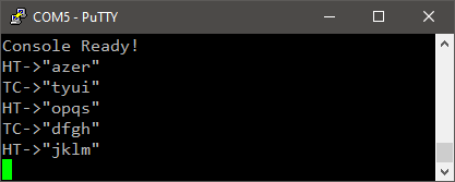
This approach to handle incoming bytes is particularly interesting when you need to parse a continuous flow of incoming bytes (e.g. NMEA messages from a GPS sensor) while saving time for other tasks. You can deal with much larger data buffer in this case. When you are warned that half a buffer is full, you know that you must process it by the time the second half is being filled, otherwise data will be lost.
| - - |
3. Summary
In this tutorial, you have learned how to receive bytes from USART peripheral using the DMA controller to automatically transfer incoming bytes to a variable in memory. In addition, you have learned how to use DMA interrupts events in a circular input buffer scenario.
- Log in to post comments