
1.2. Hello World #1 (the Cube way)
In this tutorial, you will create and run the Hello World program of embedded systems which is unsurprisingly : a blinking LED!
We'll be first using the ST-promoted way of doing this using HAL (Hardware Abstraction Layer) libraries and the Cube graphical configuration tool. I'm doing this against my will, to be honest, but beginners may find this an easy way to get started.
Yet, keep in mind all along this tutorial that this is NOT the way we will work next.
1. Create a new project
Start STM32CubeIDE and select your workspace
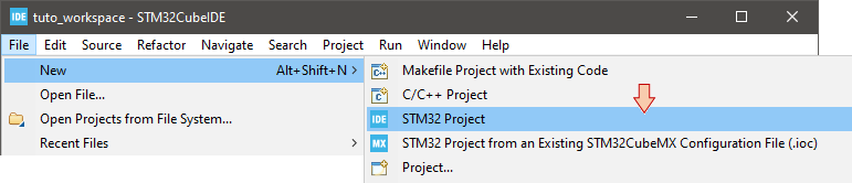
Open File → New → STM32 Project
It takes a little while for STM32CubeIDE to gather up-to-date device information from ST repositories. Wait until the process finishes.
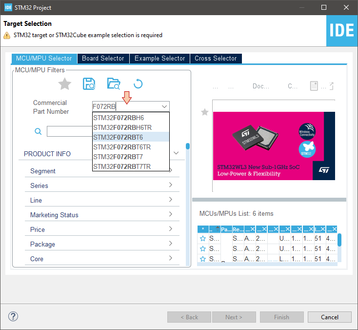
Then you'll be asked to select the target for the project. We're using STM32F072RB device in these tutorials. Since there are more than 1500 STM32 devices available, you may use the Part Number field to help searching the desired part number:
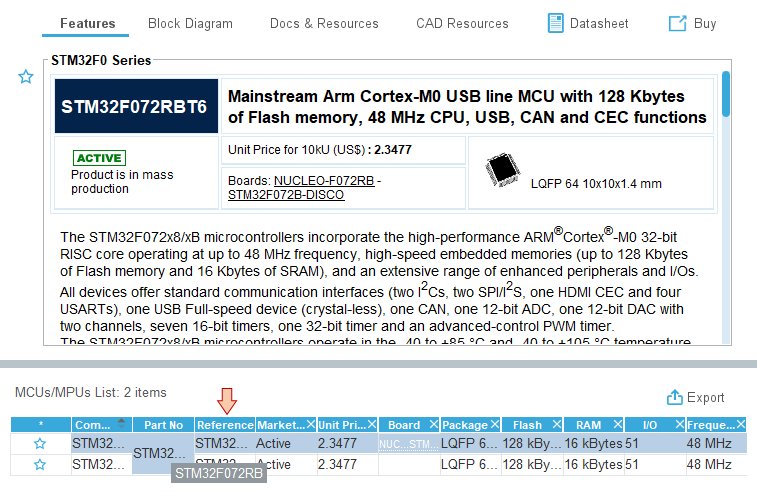
When you're left with only few choices, pick up the device that corresponds to your package. Here, we're using the LQFP64 package. Select the corresponding line and then click Next.
Give a project name ‘blink’. Use STM32Cube for the targeted project type:
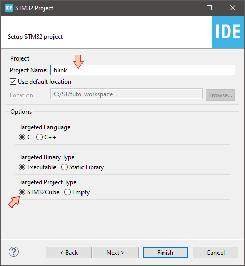
Click Finish.
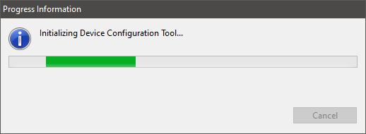
You'll be prompted to open the Device Configuration Tool. Click Yes.
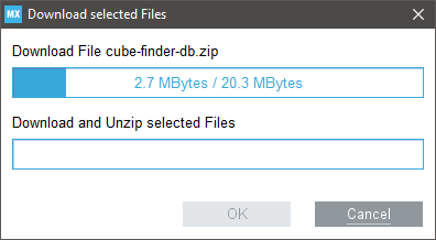
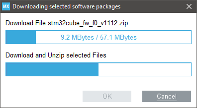
Again, it takes a little while for the project to get initialized. For new devices, you'll have to wait for the whole Cube Library to download first. Be patient, welcome to the HAL world!
By the way, note that you are currently downloading the stm32cube_fw_f0 (version 1.11.2) library package.
![]()
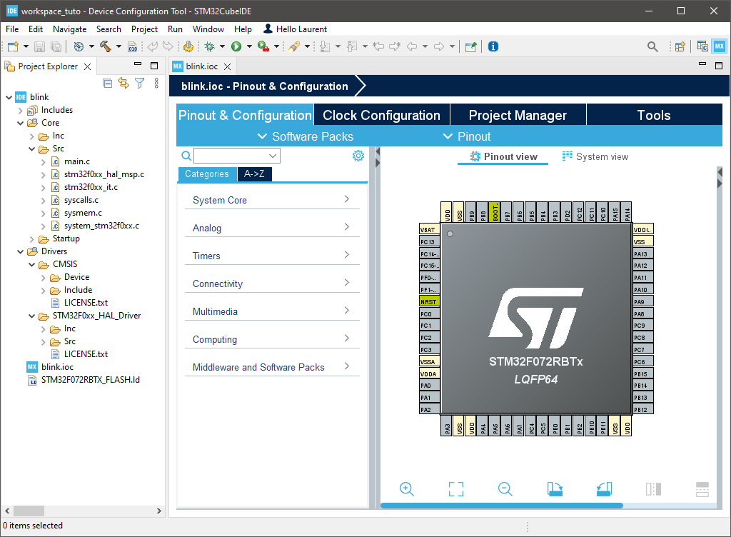
When finished, you'll end up with your project environment ready. Take a look at the tree view in the Project Explorer frame. Expanding folders reveals a pretty big number of source files (68 actually) and resources. At first start, the file blink.ioc is opened for edition in the main editor part. This file provides access to a graphical interface that offers visual way to setup the device configuration (clock, peripherals...).
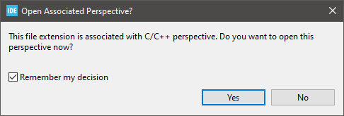
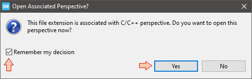
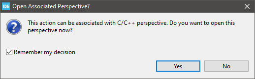
Double-click on the main.c file in the Project Explorer tree view. You'll be asked wether you want to open associated perspective. Answer Yes. You may also check the Remember my decision option to avoid further dialog boxes asking that same question. Within Eclipse, a perspective is just a specific arrangement of useful frames that depends on what you're doing at a given moment (writing code, using MX configurator, debugging, ...).
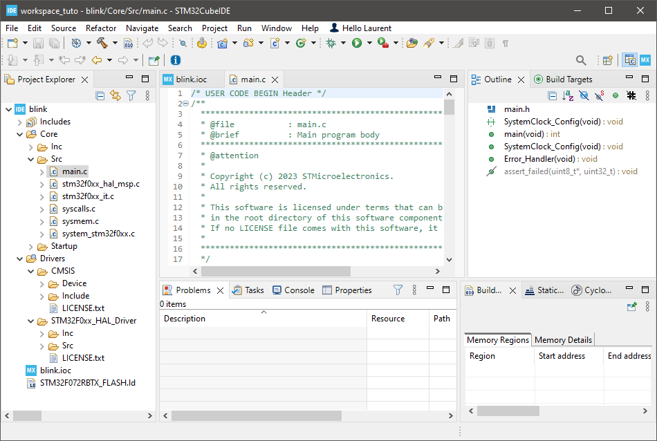
A new tab opens in the main editor area and you're ready to start with some coding:
2. Configuring LED pin
Before going on to the LED pin configuration, take a look at the main.c file content. Removing some useless comments leaves us with a pretty simple program that basically performs some initialization before entering an empty forever (infinite) loop:
int main(void)
{
  /* Reset of all peripherals, Initializes the Flash interface and the Systick. */
  HAL_Init();

  /* Configure the system clock */
  SystemClock_Config();

  /* Infinite loop */
  while (1)
  {
  }
}
The SystemClock_Config() function is written below the main() function:
void SystemClock_Config(void)
{
  RCC_OscInitTypeDef RCC_OscInitStruct = {0};
  RCC_ClkInitTypeDef RCC_ClkInitStruct = {0};

  /** Initializes the RCC Oscillators according to the specified parameters
  * in the RCC_OscInitTypeDef structure.
  */
  RCC_OscInitStruct.OscillatorType = RCC_OSCILLATORTYPE_HSI;
  RCC_OscInitStruct.HSIState = RCC_HSI_ON;
  RCC_OscInitStruct.HSICalibrationValue = RCC_HSICALIBRATION_DEFAULT;
  RCC_OscInitStruct.PLL.PLLState = RCC_PLL_NONE;
  if (HAL_RCC_OscConfig(&RCC_OscInitStruct) != HAL_OK)
  {
    Error_Handler();
  }
  /** Initializes the CPU, AHB and APB buses clocks
  */
  RCC_ClkInitStruct.ClockType = RCC_CLOCKTYPE_HCLK|RCC_CLOCKTYPE_SYSCLK
                              |RCC_CLOCKTYPE_PCLK1;
  RCC_ClkInitStruct.SYSCLKSource = RCC_SYSCLKSOURCE_HSI;
  RCC_ClkInitStruct.AHBCLKDivider = RCC_SYSCLK_DIV1;
  RCC_ClkInitStruct.APB1CLKDivider = RCC_HCLK_DIV1;

  if (HAL_RCC_ClockConfig(&RCC_ClkInitStruct, FLASH_LATENCY_0) != HAL_OK)
  {
    Error_Handler();
  }
}
And that's pretty much it.
Let us now make the Nucleo LED blinking. First thing is to configure the corresponding pin PA5 as a GPIO Output.
In the main editor, select (or open from the Project Explorer) the blink.ioc tab to bring back the graphical device configuration tool.
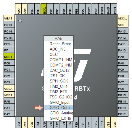
Locate and click the PA5 pin to select the behavior you want to associate with that pin. As we're going to use it to blink a LED, the corresponding function is GPIO_Output:
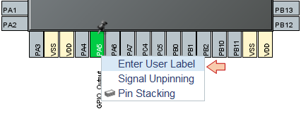
Then, right-click the PA5 pin and select the Enter User Label menu entry:
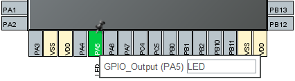
Provide a handy name to the pin such as "LED":
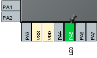
You should end-up with this:
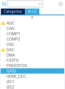
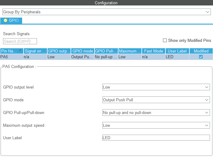
Now using the alphabetical view, explore Categories and select GPIO:
You may review all GPIO settings there. At this moment, only one pin PA5 has been associated with a GPIO function. It is configured as a Push-Pull output, with no pull resistor and a low speed. If you like, you can change settings here (e.g. speed), but those settings are OK for the purpose of LED toggling, so I suggest not changing anything.
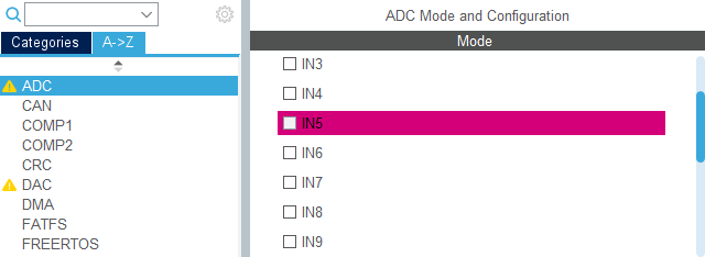
You may have observed that some other categories have been flagged with a warning sign. That's only to say that corresponding peripherals have now limited options. For instance, all ADC channels are no more available since PA5 pin, corresponding to ADC channel input 5, has been used for another purpose (GPIO). There's nothing to worry about.
3. Generating configuration code
When you are done with the device configuration, hit the code generation button ![]() in the main toolbar.
in the main toolbar.
Again, accept the perspective switching:
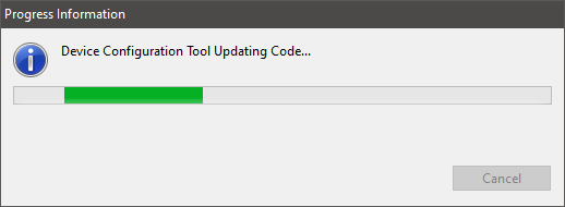
Wait until the process completes:
And here we are. New code has been automatically added to main.c.
First, in the main() function, a call to a new function MX_GPIO_Init() has appeared:
int main(void)
{
  /* Reset of all peripherals, Initializes the Flash interface and the Systick. */
  HAL_Init();

  /* Configure the system clock */
  SystemClock_Config();

  /* Initialize all configured peripherals */
  MX_GPIO_Init();                              // <-- NEW ADDED LINE

  /* Infinite loop */
  while (1)
  {
  }
  /* USER CODE END 3 */
}
Then below, one can find the implementation of MX_GPIO_Init() function:
static void MX_GPIO_Init(void)
{
  GPIO_InitTypeDef GPIO_InitStruct = {0};

  /* GPIO Ports Clock Enable */
  __HAL_RCC_GPIOA_CLK_ENABLE();

  /*Configure GPIO pin Output Level */
  HAL_GPIO_WritePin(LED_GPIO_Port, LED_Pin, GPIO_PIN_RESET);

  /*Configure GPIO pin : LED_Pin */
  GPIO_InitStruct.Pin = LED_Pin;
  GPIO_InitStruct.Mode = GPIO_MODE_OUTPUT_PP;
  GPIO_InitStruct.Pull = GPIO_NOPULL;
  GPIO_InitStruct.Speed = GPIO_SPEED_FREQ_LOW;
  HAL_GPIO_Init(LED_GPIO_Port, &GPIO_InitStruct);

}
You can finally note that new defines have been added to main.h:
/* Private defines -----------------------------------------------------------*/
#define LED_Pin GPIO_PIN_5
#define LED_GPIO_Port GPIOA
4. Get the LED blinking
As wonderful as it is, STM32CubeIDE still doesn't write core application for you! Maybe one day, AI will do that... but that's not (fortunately) for now.
Edit the main() function this way:
int main(void)
{
   uint32_t	i;

  /* Reset of all peripherals, Initializes the Flash interface and the Systick. */
  HAL_Init();

  /* Configure the system clock */
  SystemClock_Config();

  /* Initialize all configured peripherals */
  MX_GPIO_Init();

  /* Infinite loop */
  while (1)
  {
	  // Toggle LED pin
	  HAL_GPIO_TogglePin(LED_GPIO_Port, LED_Pin);

	  // Wait using a counting delay
	  for(i=0; i<100000; i++);
  }
}
Save all ![]() and hit the build button
and hit the build button ![]() . Take a look at the build console. Make sure there are no error and no warnings.
. Take a look at the build console. Make sure there are no error and no warnings.
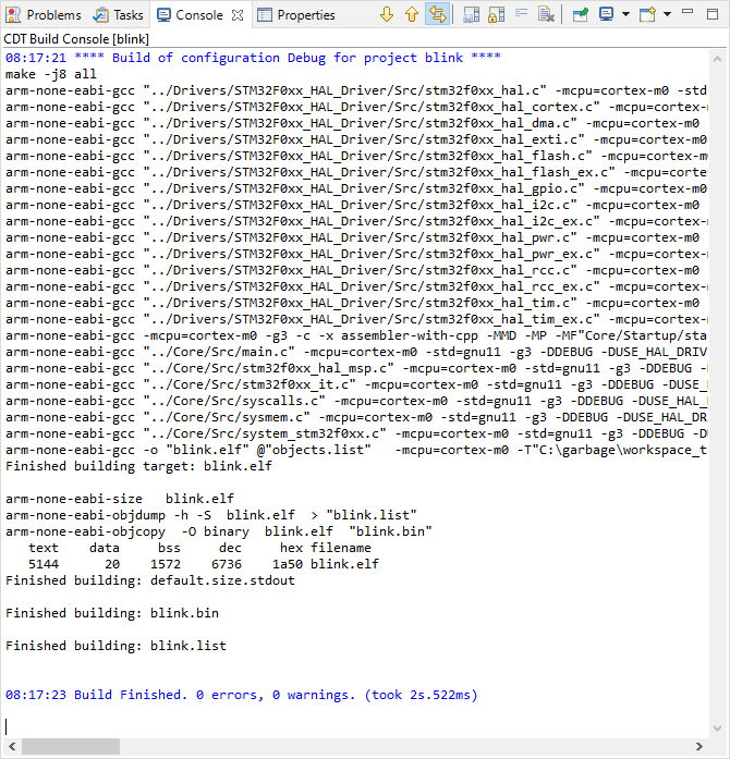
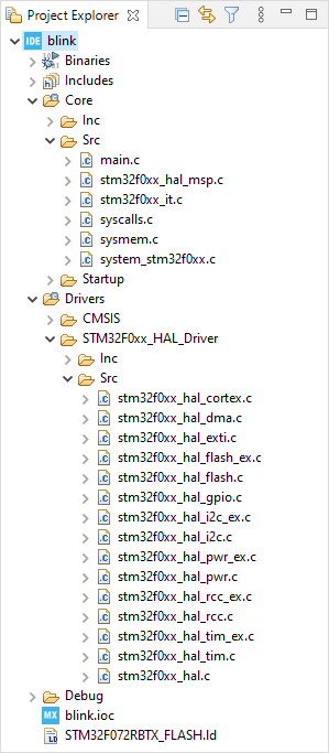
As you can see, quite a lot of source code has been built in the process. Most are HAL libraries you can see in the Project Explorer tree view by expanding the Drivers/STM32F0xx_HAL_Driver/src folder:
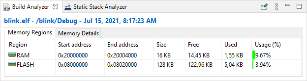
Also, take a look at the Build Analyzer to check for the amount of memory used by the program:
5. Run & Debug
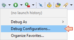
In the main toolbar, click the dropdown arrow next to the debug button ![]() and select Debug Configurations...:
and select Debug Configurations...:
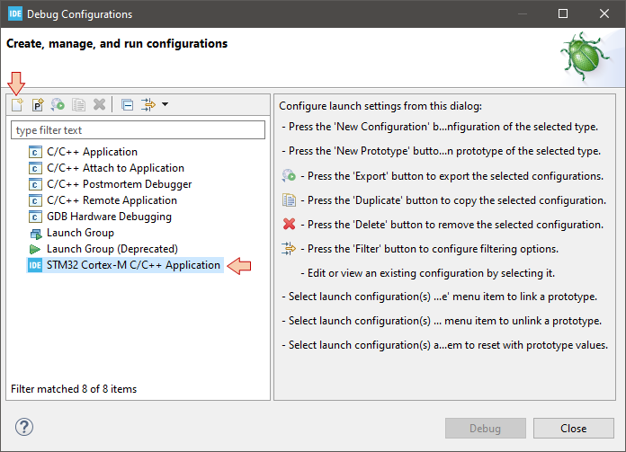
In the Debug Configuration dialog, select STM32 Cortex-M C/C++ Application, and then the New launch configuration button ![]() :
:
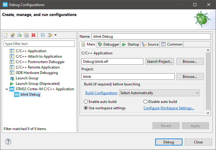
Make sure the new configuration has been created and review parameters in the Main tab:
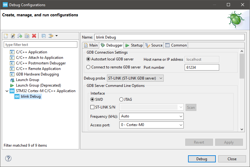
Then move to the Debugger tab and make sure that Debug probe is ST-LINK with SWD Interface:
Then click the Debug button.
You may be prompted by your firewall for network access. You must accept this. In some cases, depending on the previous life of your Nucleo board, you will also be prompted for a ST-LINK firmware update. You can refer to the previous tutorial. It is the same process as the one explained with STM32CubeProgrammer. When done, you can restart the debug session.
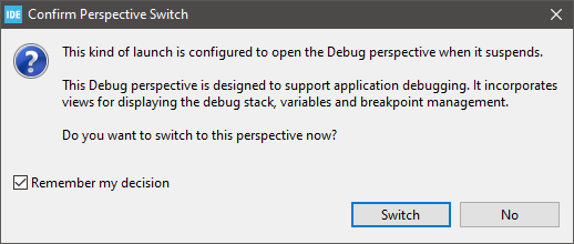
As usual, accept the perspective switch if prompted for:
You should find yourself ready for debugging:
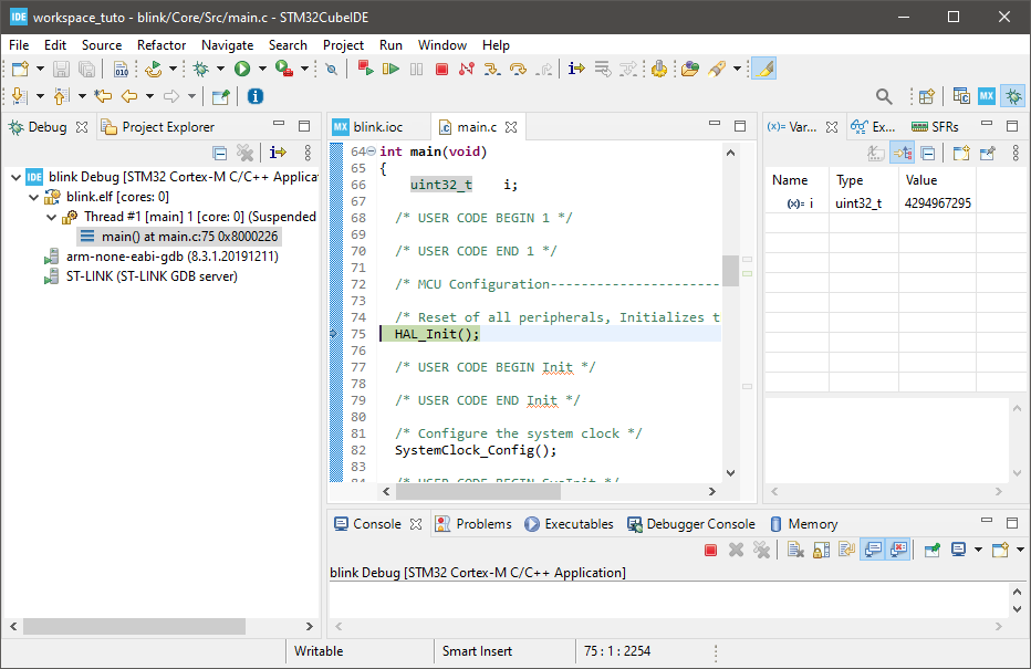
From there, you can control program execution using usual toolbar commands (![]() ,
, ![]() ,
, ![]() ,
, ![]() ,
, ![]() ,
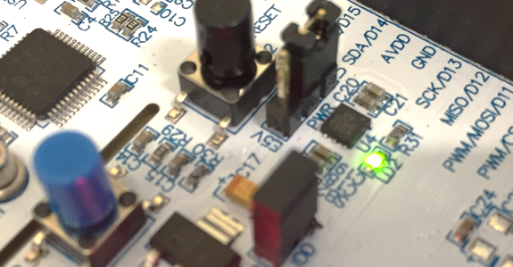
, ![]() , ...).Run the program full-speed by clicking the Resume button
, ...).Run the program full-speed by clicking the Resume button ![]() . You should get the blinking LED as expected:
. You should get the blinking LED as expected:
Then, suspend the debugger ![]() and terminate
and terminate ![]() the debug session and switch back to C/C++ perspective.
the debug session and switch back to C/C++ perspective.
Pretty easy, don't you think ?
6. Final thoughts
I'm deeply convinced that it is a mistake to start learning embedded systems programming using graphical code configuration tools because it hides many fundamental concepts that you need to understand first. IMHO, these tools should be used only by advanced users who know what they're doing, and with productivity and portability concerns (and not because of laziness). Besides, I have several examples in mind where I've been able to obtain specific non-standard behavior from peripherals that was not (or badly) supported by standard libraries.
Anyway, mastering HAL libraries requires its own level of expertise. It is another learning curve to climb that keeps you away from the STM32 hardware somehow. That is clearly not the path I want to promote here, and if you think that this is not for you, there are bunch of tutorials on the web to get you started with HAL.
- Log in to post comments