
1.2. Parametric Sweep
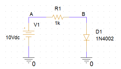
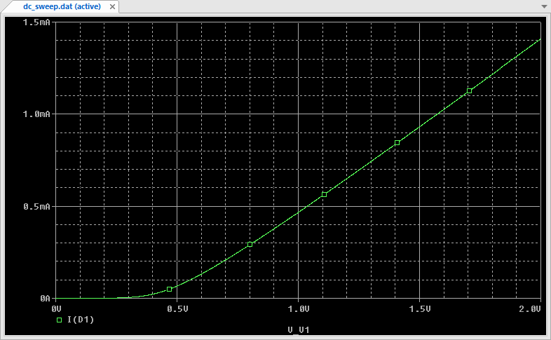
This tutorial assumes that you've completed previous tutorial, and that you've got a working simulation profile performing DC Sweep of the V1 voltage source (from 0V to 2V) while monitoring the current flowing through the diode D1.
1. Defining a Global Parameter
Imagine we want to study the effect of a change in the resistor value in the above DC sweep. Would it be possible to automate several simulation runs for various values of R1? The answer is yes.
To to that, we need to specify that R1 value is no more fixed (1k$\Omega$), but instead is a parameter 'res' (the name is up to you), which default value can be 1k$\Omega$ if you like.
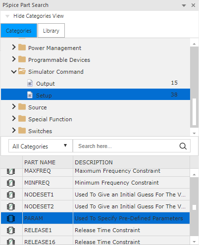
In order to achieve this, we need to place a special part onto the schematic. That part belongs to the SPECIAL libary, and is named PARAM:

Once you got the PARAM part placed in the schematic, you'll need to edit its properties. There's two ways to open the part properties editor :
Double-click on the part into the schematic
Or, select the part with left-click, then right-click and choose Edit Properties... from the contextual menu
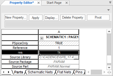
The part properties editor opens as a new tab. You may need the Pivot button to display the multiple properties vertically as shown below:
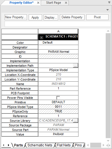
To instantiate a new global parameter, we need to add a new property to the PARAM part. In the top ribbon, click the ![]() button.
button.
Then, complete the dialog window:
Provide a name the for the new property ('res' for instance here)
Provide a default value, which will be used if not overridden elsewhere
Make sure that Display [ON/OFF] option is checked
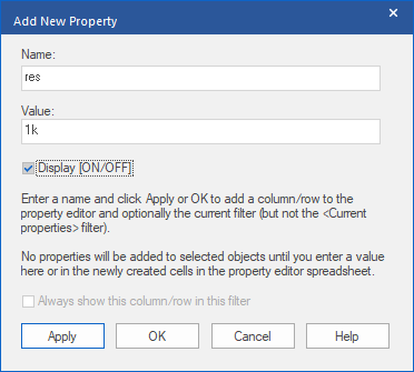
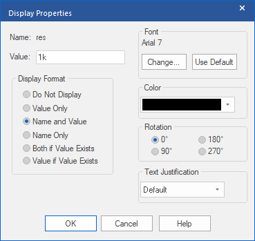
Click OK. A second dialog opens. Select Name and Value as the Display Format, then click OK.
At the end of the process, you should see the newly created property 'res' in the list, with its default value. Done!
Save the properties ![]() and then close the properties editor tab.
and then close the properties editor tab.
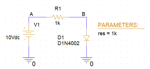
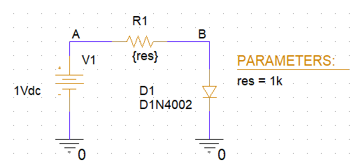
Below is the schematic as it looks now:
2. Associating a Design Parameter with a Global parameter
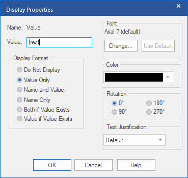
Double-click the '1k' value below R1 resistor. Time has come to turn this fixed value into a parameter. In the dialog box, change the Value field from 1k into {res} then click OK.
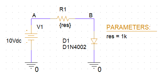
Save the entire design and re-run ![]() the DC sweep simulation. Hopefully, nothing has changed. R1 is now {res}$\Omega$, with {res}=1k$\Omega$, so there's nothing new. Still, this is an important verification saying that resistor value is correctly linked to the 'res' global parameter.
the DC sweep simulation. Hopefully, nothing has changed. R1 is now {res}$\Omega$, with {res}=1k$\Omega$, so there's nothing new. Still, this is an important verification saying that resistor value is correctly linked to the 'res' global parameter.
3. Global parameter as a Parametric Sweep Variable
Now it's time to play!
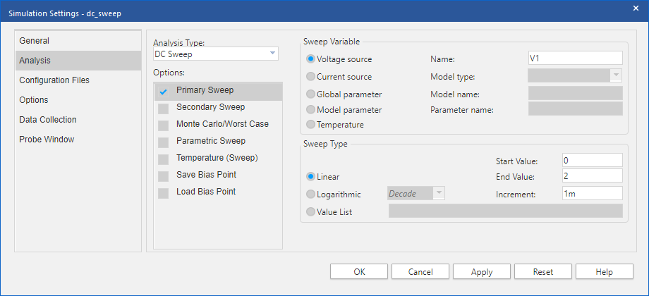
Edit ![]() the dc_sweep profile settings. Keep the Primary Sweep unchanged. The Primary Sweep is basically what will be the x-axis of the simulation result plot. The voltage of V1 source is the primary variable (varying from 0 to 2V).
the dc_sweep profile settings. Keep the Primary Sweep unchanged. The Primary Sweep is basically what will be the x-axis of the simulation result plot. The voltage of V1 source is the primary variable (varying from 0 to 2V).
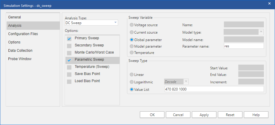
Then, activate the Parametric Sweep. The Parametric sweep enables a second variable.
x-axis variable is not changed, but instead of getting a single trace, you'll get a family of traces for each value of the second variable. There are different ways to specify the second variable values. The screen shot below is an example of asking the simulator to perform the DC Sweep for 3 specific cases of R1: 470$\Omega$, 820$\Omega$ and 1k$\Omega$:
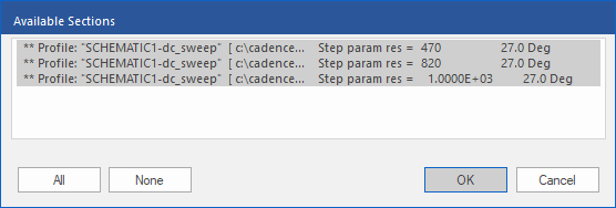
Click OK and run ![]() the simulation. When its done, the PSpice
the simulation. When its done, the PSpice ![]() result window lets you know that 3 simulations are available. Make sure all 3 are selected, then click OK.
result window lets you know that 3 simulations are available. Make sure all 3 are selected, then click OK.
And you got the expected family plot:
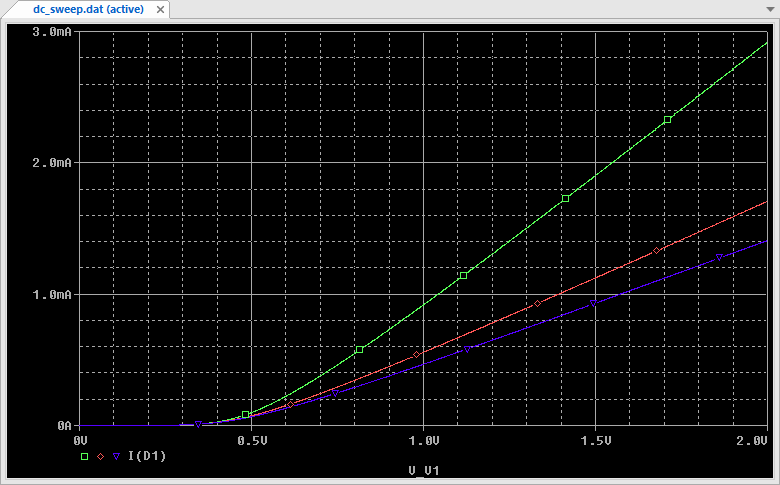
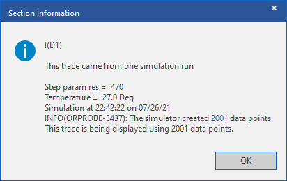
Traces are displayed in the same order as the value list in the simulation profile. Nevertheless, trace legend is not clear. You may select a trace, and then from the contextual menu (right click) choose Trace Information. This is what you get if you ask for information about the red trace in the screenshot above:
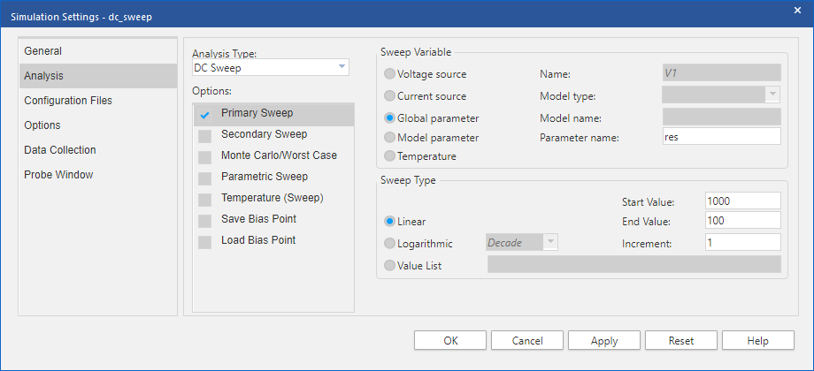
4. Global parameter as a Primary Sweep Variable
To finish, let us go thru a practical example: Assume we need to find out which resistor value would provide a 2mA biasing current for the diode, under a power supply V1=1V. A plot with res parameter as x-axis would be nice!
We can use the resistor value as our primary sweep (and no secondary sweep). Let's give a chance to resistors values in the range 100$\Omega$ → 1k$\Omega$, with a fine step of 1$\Omega$:
Make sure V1 has been set to a constant DC voltage of 1V:
And then run ![]() the simulation and plot
the simulation and plot ![]() the result :
the result :
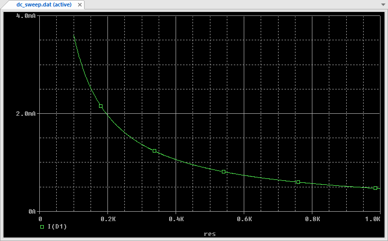
From the above plot, 2mA is reached with R1≈200$\Omega$.
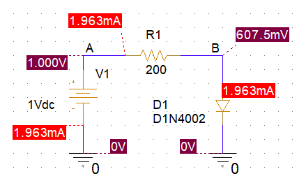
You may now replace the value of R1, from the res parameter to the above result, and (re)run the bias simulation to make sure this is working:
It would have taken much longer to search with a trial and error approach. Yet, using simulation to obtain this result was maybe a little bit overkill... Using the usual first-order approximation:
\(V_{D1} \approx 0.6V\)
We get:
\(R_1 = \frac{V_R1}{I_D1} = \frac{(V_1 - V_{D1})}{I_D1} \)
\(R_1 = \frac{(1-0.6)}{2.10^{-3}} = 200\Omega\)
Not too hard...
Anyway, the above example doesn't really matter. You can retain from this tutorial that virtually 'anything' can be used as primary sweep and therefore can be investigated as x-axis variable in a DC Sweep simulation. When using a secondary sweep variable, you obtain a trace family sharing the same primary sweep, and therefore the same x-axis.
It's now up to you to imagine how all this possibilities may help in the context of real case studies.
- Log in to post comments