
1.5. Importing SPICE models
This tutorial covers the situation where you want to simulate a component (integrated circuit) that's not provided by any Cadence libraries. To do that, you will need a SPICE model for that component. Tools are there if you plan to create your own model, but that requires a thorough knowledge of the circuit and usually involves a characterization campaign.
1. Prerequisites : A SPICE model
For commercially available analog integrated circuits, it is a common practice for manufacturers to provides SPICE models. ST©, Analog Devices©, Texas Instruments©, Linear Technology© for instance do provide SPICE models for several of their analog products.
Here, I'll be illustrating the matter with a device from THAT Corporation. THAT is an IC design house that built a strong reputation over the years in the professional audio field with some really unique devices.

Let us consider the 2180 VCA series for instance. A VCA (Voltage Controlled Amplifier) is basically an amplifier, whose gain is controlled by means of additional inputs. Such circuit can be used for amplitude modulation, and more commonly for dynamic processing of audio signals. A dynamic processor adjusts in real-time the gain of the amplifier stage in order to keep the output amplitude under control. Such process is also called AGC (Automatic Gain Control) and is a very common feature of several analog processing chains.
THAT provides SPICE models for their device range. You can download a zip archive from there.
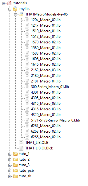
Download and extract the 'THATMacroModels-Rev05' archive. It is a collection of .lib files containing SPICE macro-models (one for each device in their catalog):
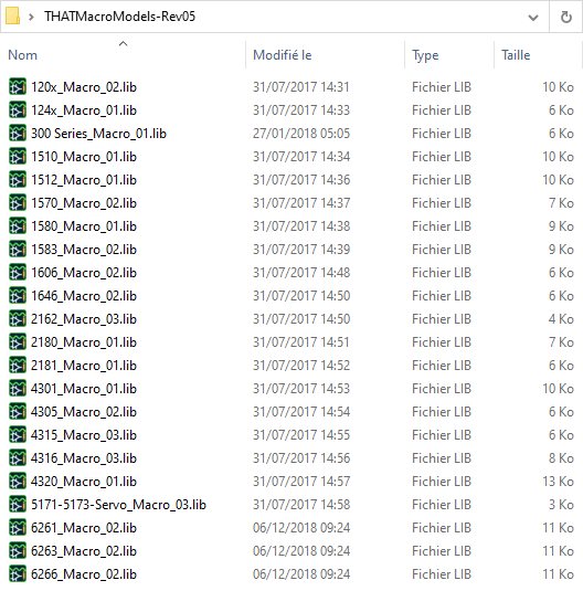
A SPICE macro-model is actually a text file you can open. Open for instance the '2180_Macro_01.lib' file with your choice of text editor:
* ========================================================================
* THAT 2180A VCA SPICE Macromodel, Beta Version 1.B4 12/30/97*
* Copyright 1997 THAT Corporation, all rights reserved.
*
* Rev 01 RB 6-9-17
* Changed names for THAT2180A, THAT2180B, THAT2180C
* Changed pin names to match datasheet
*
*
* Note: Macromodel net numbers correspond to the IC package numbers.
* Pin 4 is not used on the 2180-series VCAs.
*
*                 Iin
*                  |  Ec+
*                  |   |   Ec-
*                  |   |   |  Vee
*                  |   |   |   |  GND
*                  |   |   |   |   |  Vcc
*                  |   |   |   |   |   |  Iout
*                  |   |   |   |   |   |   |
.SUBCKT THAT2180A  1   2   3   5   6   7   8
*
*
*
R1         10 13  2.5k
R2         10 14  2.5k
I1         10 29 DC 50uA
R3         11 7  8k
R4         12 7  8k
G1         7 15 11 12 1.25e-4
R5         0 15  10MEG
R6         0 16  10k
C1         16 15  10p
R7         19 7  2k
G2         19 20 15 0 5e-4
C2         19 7  8p
E1         20 28 30 6 2
R8         5 29  1.7k
V1         0 29 DC 2.1V
I2         0 30 DC 20uA
R9         4 2  27
C3         20 0  12p
I3         20 28 DC 220uA
V2         18 0 DC .7V
V3         17 15 DC 1.4V
Q1         11 1 13 QNHIB
Q2         12 9 14 QNHIB
Q3         20 21 23 QNPNNOM
Q4         20 22 24 QNPNNOM
Q5         8 4 27 QNPNNOM
Q6         1 25 26 QNPNNOM
Q7         1 2 23 QPNPNOM
Q8         8 3 24 QPNPNOM
Q9         28 28 27 QPNPNOM
Q10        28 28 26 QPNPNOM
Q11        28 29 5 QNPNNOM
Q12        30 30 31 QNPNNOM
Q13        0 0 31 QPNPNOM
D1         18 15 DNOM
D2         17 7 DNOM
R10        3 25  20
R11        22 20 20
R12        21 20 27
Vos        9 6 DC 3mV
Isym       0 4 DC -420nA
*    Isym = -420nA for typical THD.  Set to -1uA for worst case THD.
.model qnpnnom npn (is=1e-15 bf=200, vaf=110, cjc=3pF)
.model qpnpnom pnp (is=1e-15 bf=100, vaf=85, cjc=5pf)
.model qnhib npn (bf=16000)
.model dnom d (is=1e-15)
.ENDS
As you can see, the simulation model is provided as a SPICE sub-circuit (.SUBCKT) netlist. That's something usual for device manufacturers, so if you can find a similar netlist for the device of interest, then you're ready to go. If not, then it probably means that there is no model available and that you will not be able to run simulations.
Note in the above example, that actually 3 versions of the 2180 VCA device are available as 3 distinct models (namely THAT2180A, THAT2180B, THAT2180C). These 3 versions (A,B,C) relates to the calibration precision of the device (and hence the price...). We'll use only one version (THAT2180A) in the following.
As we have everything we need, let us put this into the Cadence framework!
2. Creating a Capture Library
Start ![]() Capture and create a new project (e.g. 'tuto_3').
Capture and create a new project (e.g. 'tuto_3').
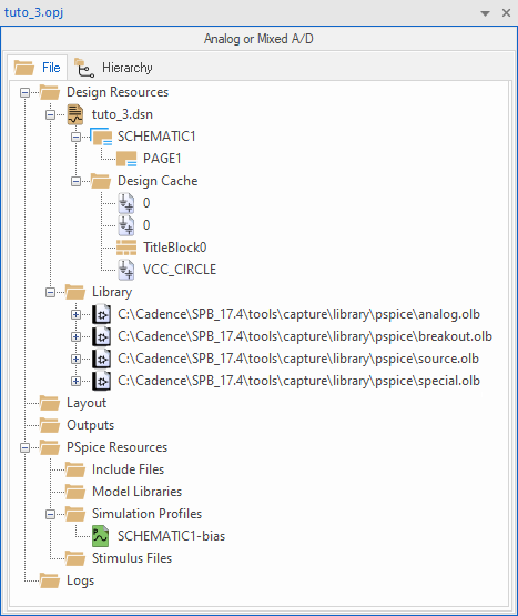
The initial structure of your empty project should be something similar to this:
Within Capture, any component (device) is a Part belonging to a Library. We therefore need to create a new library to host our new parts.
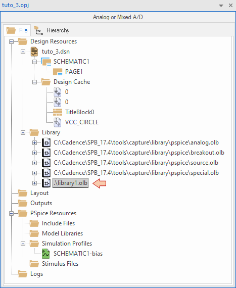
From the main menu select File → New → Library. A new library appears with a default temporary name library1.olb.
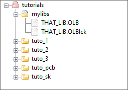
At this moment, the library is not saved yet. Right-click on the library name and then Save As... Carefully choose a name and a location for your library. You may for instance create a folder P:\Cadence\tutorials\mylibs\ and call that library that_lib since we'll use it to collect THAT devices. You better store your libraries outside any project folder since the purpose of a a library is to serve several projects:
Once saved, the library is a part of your project structure:
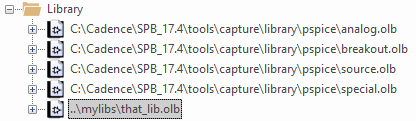
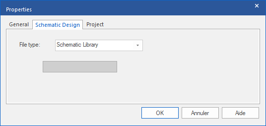
Right-click on the library in this tree view and then select Library Properties. Make sure the File type is a Schematic Library:
Finally, move the 'THATMacroModels-Rev05' folder including all THAT device macro-models into the same mylibs\ folder so that everything is regrouped in one place.
3. Adding a Part into the Library
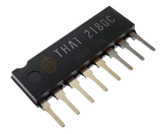
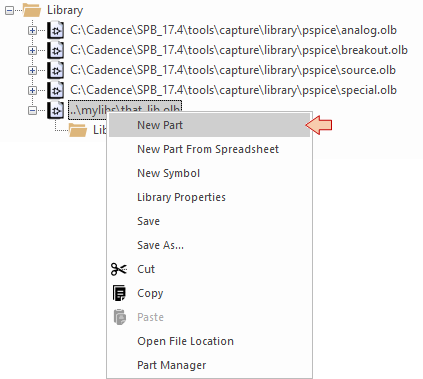
Let us now add the THAT2180 device symbol into our library. This device is sold into a single-row, 8-pins plastic package:
From the library contextual menu (right-click), select New Part.
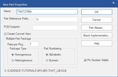
Provide a name to the part 'THAT2180A' and leave other field as is, then click OK.
This will:
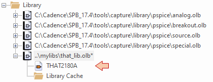
add the THAT2180A as a new part in your library:
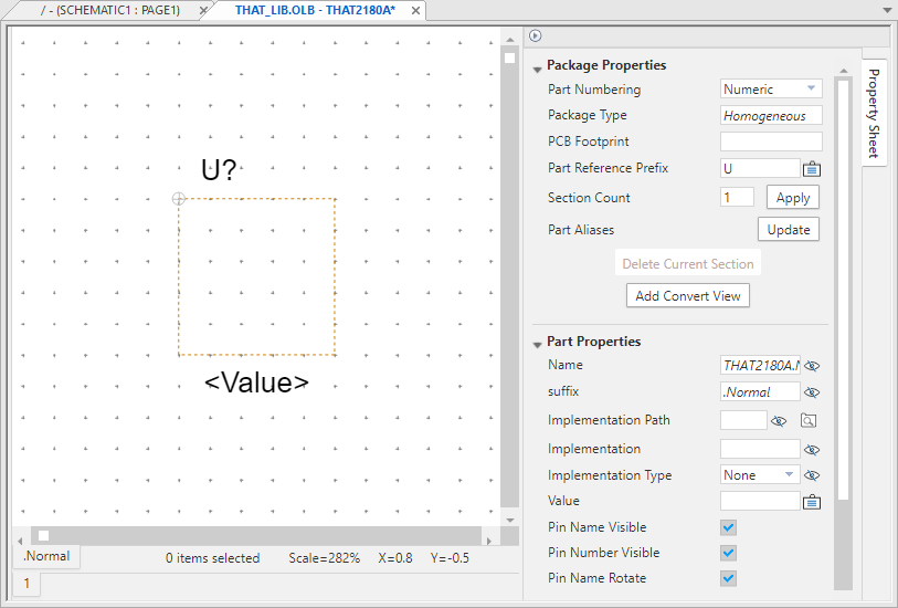
And open the part editor:
Time has come to draw a symbol for the THAT2180A device. A symbol is basically a shape (rectangle, triangle, circle, lines) and the pins. Only pins really matters in a symbol, so that regarding the shape, you can basically do whatever you want (including nothing). Yet, just like a common language is important for humans to communicate, there are some standards in the electrical engineering field that are there to help people understand each other. Traditionally, the symbol shape of an amplifier is a triangle... not my fault.
You can get inspiration from the THAT2180 datasheet:
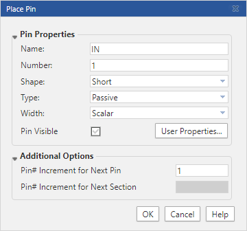
Start by creating the pins. Use the ![]() Place Pin button. For each of the 8 pins, complete the Place Pin dialog as follow :
Place Pin button. For each of the 8 pins, complete the Place Pin dialog as follow :
| Name | Number | Shape | Type |
| IN | 1 | Short | Passive |
| EC+ | 2 | Short | Passive |
| EC- | 3 | Short | Passive |
| SYM | 4 | Short | Passive |
| V- | 5 | Short | Power |
| GND | 6 | Short | Power |
| V+ | 7 | Short | Power |
| OUT | 8 | Short | Passive |
For instance for pin #1:
Note that the ![]() Snap To Grid feature must be engaged all along pin placement. You have to perfectly align pins with the grid otherwise wires will not connect later at the schematic level.
Snap To Grid feature must be engaged all along pin placement. You have to perfectly align pins with the grid otherwise wires will not connect later at the schematic level.
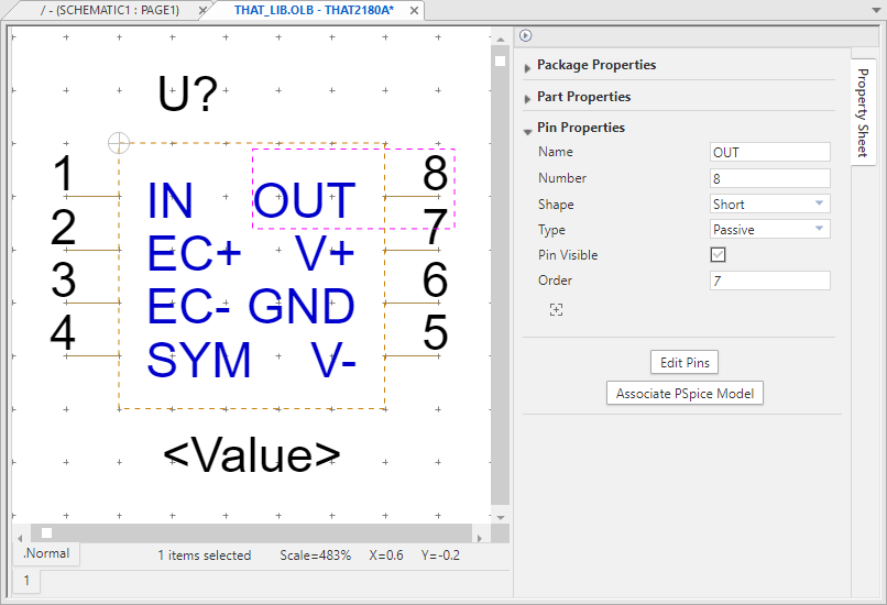
You may end-up with something like this, which is valid as a symbol, yet with no shape, it does not help reading when placed into a schematic. Note that you can review and edit the pins properties from here also.
You're now allowed to play with the shapes toolbar, and to create some art!
![]()
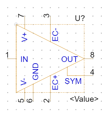
You can disengage the grid snapping when drawing shapes, but don't forget to turn it on when you move pins. Here is an example of what you may achieve:
4. PSPICE model association
Save your symbol, but do not leave the part editor yet.
Before we can associate the symbol with its SPICE model, we have a small issue here to deal with... It concerns the pin #4 (SYM) that does not appear in the SPICE model. That's a problem because SPICE association requires all the symbol pins to be associated with the model terminals.
* Note: Macromodel net numbers correspond to the IC package numbers.
* Pin 4 is not used on the 2180-series VCAs.
*
*                 Iin
*                  |  Ec+
*                  |   |   Ec-
*                  |   |   |  Vee
*                  |   |   |   |  GND
*                  |   |   |   |   |  Vcc
*                  |   |   |   |   |   |  Iout
*                  |   |   |   |   |   |   |
.SUBCKT THAT2180A  1   2   3   5   6   7   8
You understand that the problem arises from the chosen example. Hopefully, with the device you'll have to deal with, you won't have such trouble. There are few possible workarounds for this issue:
First solution would be to simply remove the SYM pin #4 from the Cadence symbol. This works well, but I'm not keen doing this because we may need a complete symbol for subsequent PCB design. In this case, we need the number of pins in the part symbol to exactly match the number of physical pins (8) of the real device. Doing so, part symbol and PCB footprint association is possible. Of course we could cope with two versions of the THAT2180A device. One with 7 pins for simulation, and another with 8 pins for PCB design. Not quite terrific...
A second solution would be to set SYM pin #4 as an invisible power pin. That's not what it is, but that would do the trick. Yet, an invisible pin is... invisible! That's not what we want either for the sake of schematic clarity.
A third approach would be to edit the SPICE macro-model in order to add a fake 8th terminal so that we have a match with the part symbol.
Let's do that.
Open the '2180_Macro_01.lib' file into a text editor and do the following edit:
For each device version (A,B,C) add an extra 8th pin at the end of the terminal list. Unfortunately, we can't use number #4 since it's been used in the netlist as a regular net. Let's number this additional pin with an arbitrary #99 to make sure it does not exist in the netlist.
* ========================================================================
* THAT 2180A VCA SPICE Macromodel, Beta Version 1.B4 12/30/97*
* Copyright 1997 THAT Corporation, all rights reserved.
*
* Rev 01 RB 6-9-17
* Changed names for THAT2180A, THAT2180B, THAT2180C
* Changed pin names to match datasheet
*
*
* Note: Macromodel net numbers correspond to the IC package numbers.
* Pin 4 is not used on the 2180-series VCAs.
*
*                 Iin
*                  |  Ec+
*                  |   |   Ec-
*                  |   |   |  Vee
*                  |   |   |   |  GND
*                  |   |   |   |   |  Vcc
*                  |   |   |   |   |   |  Iout dummy
*                  |   |   |   |   |   |   |    |
.SUBCKT THAT2180A  1   2   3   5   6   7   8    99
A model terminal can't be floating. Let's then connect our fake pin to GND through a huge $10G\Omega$ resistor. Simply add the following line at the beginning of the netlist (again, for the 3 device version):
R99 99 0 10G
OK, that should be enough to get the model association working. Save the '2180_Macro_01.lib' file and close the text editor.
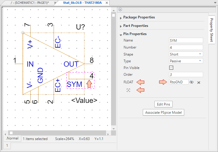
Since the SYM pin is not included into the SPICE modeling, what we want at the schematic level is to leave it floating. If we do nothing, we'll get a warning and we'll not be able to run a simulation. We therefore need to add a new property to the pin #4.
In the part editor, select the SYM pin #4 and click the ![]() Add Property button. Select the FLOAT property and set its value to 'RtoGND' as shown below.
Add Property button. Select the FLOAT property and set its value to 'RtoGND' as shown below.
Almost done.
Click the ![]() button in the part editor.
button in the part editor.
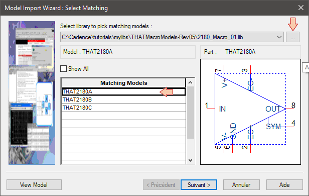
In the Model Import Wizard, use the browse button and navigate to the '2180_Macro_01.lib' file. If you did the above trick well, the three devices THAT2180A, THAT2180B, THAT2180C should be listed as possible Matching Models. Note that matching only means that the number of model terminals corresponds to the number of part symbol pins. Nothing more...
Select THAT2180A and then click Next.
Now perform the pin association by selecting the correct Symbol Pin for each Model Terminal. Remember that model terminal #99 has been added to fake the SYM pin:
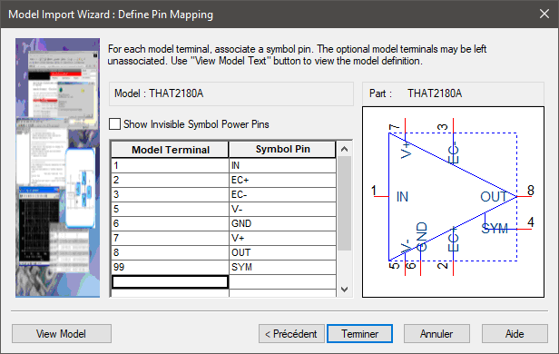
Click Finish when done.
Save ![]() your part, then close the THAT2180A editor tab. Congratulation, you've just created a new library, hosting a new part that you can place in a schematic, and simulate. Nice!
your part, then close the THAT2180A editor tab. Congratulation, you've just created a new library, hosting a new part that you can place in a schematic, and simulate. Nice!
Want to try?
5. Let's simulate
At this moment, your project structure should be similar to this:

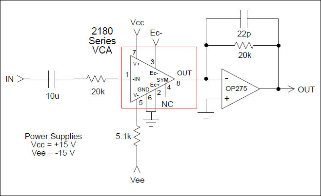
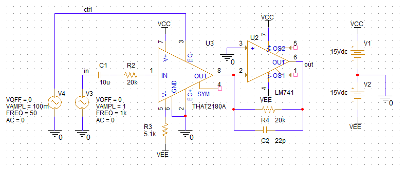
Open the schematic editor (double-click PAGE1) and edit your simulation test case. Here I'm just using the typical application circuit from the THAT2180 datasheet. Note that THAT2180 VCAs are Iin/Iout devices. That the reason for having resistor R2 at the input, and the I/V converter stage around the LM741 opamp at the output. The controlling voltage applied to EC- input is a low-frequency sine-wave provided by V4. Together with the VCA, this source performs an amplitude modulation of the carrier sine-wave delivered by V3.
Let's see if this is working!
Create a TRAN simulation profile in order to compute few periods of the modulating source (100ms) with a good resolution (10µs):

If you try to run the simulation at this moment, you'll get an error saying that subcircuit for the THAT2180A part is missing.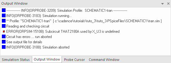
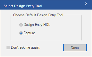
From the Capture main menu, select New → PSpice Library. Select Capture as Default Design Entry Tool, then click Done.
In the AMS Model Editor window, select File → Open and navigate to the '2180_Macro_01.lib' file.

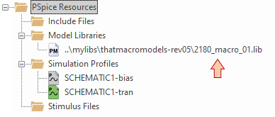
Have a look on the 3 model versions and simply save the library ![]() . That will add the model library to your project structure.
. That will add the model library to your project structure.
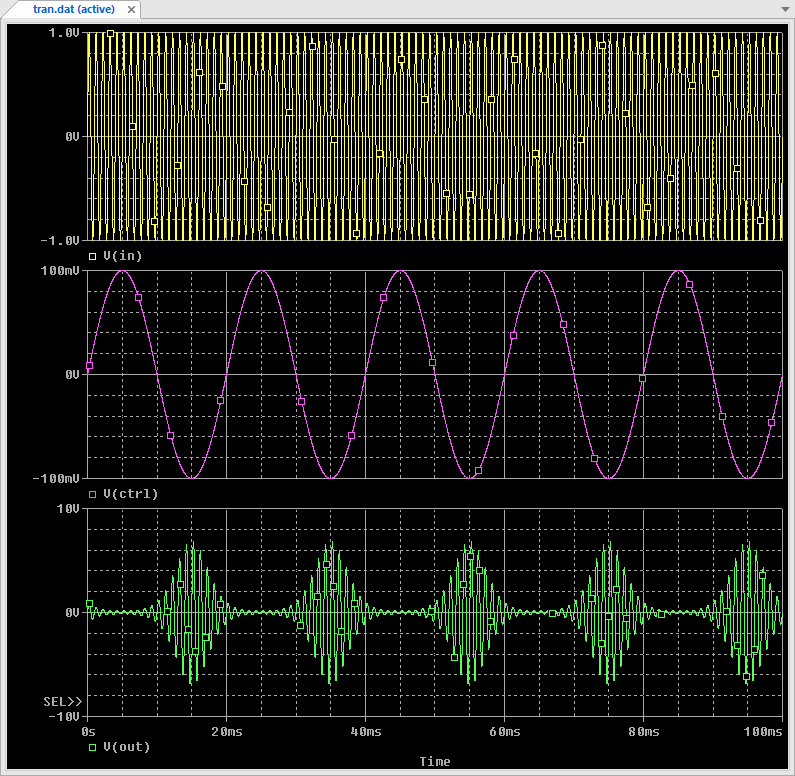
Now you can run ![]() the transient simulation profile and feel good about the result!
the transient simulation profile and feel good about the result!
Congratulations!
- Log in to post comments