
2.3. Part Integration I: Schematics
Say you want to integrate a new part into a schematic that does not exist in the available libraries. Well you need to create your own library, and then add parts you want into that libary. It's that simple.
In this tutorial, we'll see how to create a new library, then add a part into that library. Custom PCB footprint is addressed in a separate tutorial.
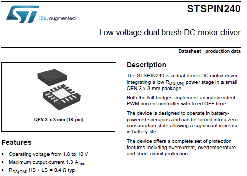
As an example, let-us consider the STSPIN240 motor driver from ST. The first step is to get the device datasheet on the web:
1. Creating a new library
Start ![]() Capture application.
Capture application.
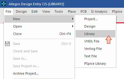
From the start page, select File→New→Library. Note that here, I'm assuming that you don't have a personal library yet. If you have one, you may choose to open an existing library instead. A library is a collection of several components (parts). It's up to you to create one or several libraries to collect your various DIY parts.
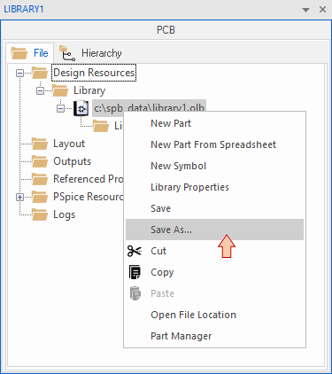
The library is created with a default name and location. You may want to rename that library, and choose a personal location on your private disk space. Use the contextual menu to perform a Save As...
In this example, the library is saved as "my_lib.OLB" in my personal tutorials directory structure:
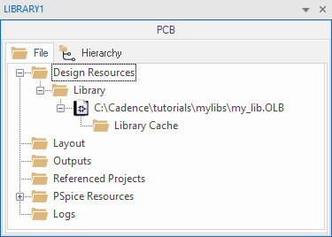
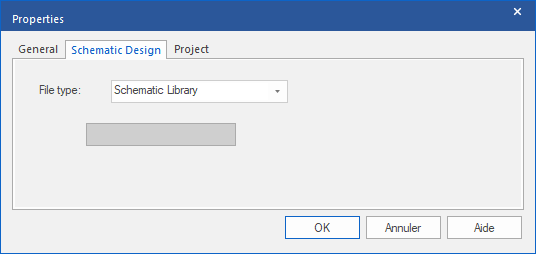
You may also verify that the new library is a Schematic Library by checking its properties (right-click):
2. Add a new part
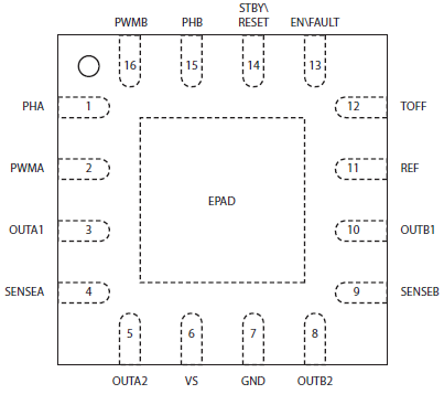
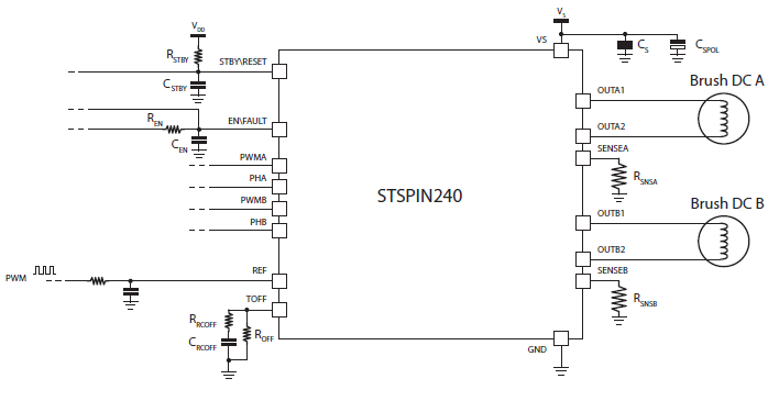
Time has come to add a new part (i.e. a component) into your library. Make sure you can find the pinout description of your device into the datasheet. You basically only need a table or a drawing with pin names and associated numbers. For the STSPIN240, we have this:
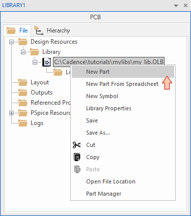
From the library contextual menu, select New Part:
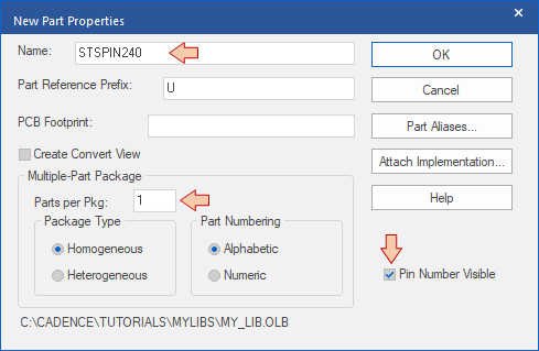
Give a name to your component "STSPIN240". You may also want to check other options, such as the Parts per Pkg number. For some devices such as opamps (e.g. TL072, LM324) or logic gates, it is common to find several instances of the same component in one single package. This is not the case here, so 1 is fine. You may click OK.
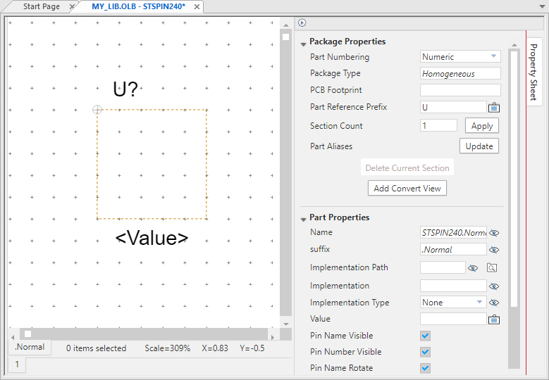
The part editor window opens:
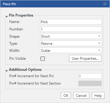
You can start adding pins ![]() according to the device datasheet. Keep names and number consistent with the device pinout. For our purpose of schematic editing and basic PCB routing, the "short" shape and "passive" type will suit most pins (especially when you don't know the exact function of the pin). You may choose the "power" type for supply pins (e.g. VCC, GND, and alike) but it doesn't really matters here.
according to the device datasheet. Keep names and number consistent with the device pinout. For our purpose of schematic editing and basic PCB routing, the "short" shape and "passive" type will suit most pins (especially when you don't know the exact function of the pin). You may choose the "power" type for supply pins (e.g. VCC, GND, and alike) but it doesn't really matters here.
Make sure that the snap to grid ![]() option is engaged. It is very important that pins are perfectly grid-aligned. If not, that will cause wrong connections at schematic level when you'll instantiate that part later.
option is engaged. It is very important that pins are perfectly grid-aligned. If not, that will cause wrong connections at schematic level when you'll instantiate that part later.
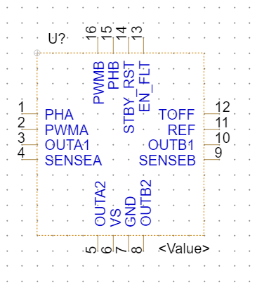
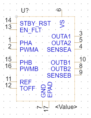
Once your done creating all the pins, you'll end up with something like this. Note that you'll have to resize the device boundaries by dragging corners to fit all the pins:
It is a good idea to start placing pins the same way it is physically ordered on the real device. Doing so, you can easily make sure that nothing is missing. Nevertheless, physical arrangement is not always good for schematic clarity and you may prefer to order pins in a more "purpose-based" manner. Sometimes, application schematics available in the datasheet can help considering another pin ordering. Doing so, you must not change the pin numbers. You only change the way the symbol looks:
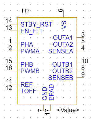
That's leading us to something more like this (just dragging pins and adjusting boundary size and adding the thermal pas as pin #17). The placement logic here is to have inputs on the left, outputs on the right hand side, and power supply coming from top and bottom. Again it is only about aesthetics and schematic clarity.
What only matters is the pin list (with correct numbers and names). Note that the thermal pad (EPAD) was given a pin number also. That is necessary because is it mentioned in the datasheet that this pad must be connected to GND. Therefore, there will be an associated PCB pad for this pin and the number of pins in the schematic MUST match the number of pads in the (coming) PCB footprint.
Let us finally draw a rectangle above the part boundaries using the shape toolbar:
![]()
Save the part ![]() . You're done creating the schematic view of the part.
. You're done creating the schematic view of the part.
You may check that your library now holds your new part:
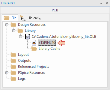
Congratulations, you can now use "my_lib.OLB" library to add the STSPIN240 part to any schematic you want.
- Log in to post comments